QUOTE (mcgyver @ Jan 7 2015, 08:36 AM)

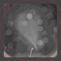
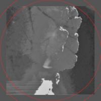
I found a third moving dot in the images, and shadows direction does not allow supposing one dot is a shadow.
I was tipping more in the direction of 'possible camera artifact' for those little dots, but finding a 3rd one really does push it much more in the direction of some kind of real objects flying above the surface. For one thing, Object #3 seems to have a fairly distinctive long, thin shape that appears to have rotated between the two images. To me, Objects #1 & #2 look more like possible 'bad pixels' on the camera but Object #3 doesn't look like a bad pixel at all, due to its shape, and particularly its changing shape from image to image.
I spent some time in STK 'observing' this area of the comet from the viewpoint of Rosetta and then comparing what I saw there to what I see in these two images, in the area of the three objects. A few thoughts based on that:
- "Montage" appears to be first in time and "Mosaic" a bit later in time.
- That means the objects are moving down and to the left in terms of the image
- That appears to mean the objects are moving close to due west, ie opposite direction of rotation. So, perhaps (?) a similar scenario to that we've been discussing upthread, where debris is spewed from vents; if they are expelled with any upwards velocity they tend to move westward relative to the surface of the comet because of the fast rotation rate of the comet surface and the fact that an object rotates at a slower speed than the surface the further from the axis of rotation it rises.
- The time between the two photos appears to be in the range of approx. 3 minutes to 5 minutes, maybe a bit more or less. It is definitely more than, say, 1 minute and less than, say, 15 minutes. That is just my impression based on stepping the view in STK by various time periods and looking; I'm not sure exactly what you could measure to nail this down more precisely.
- If you assume all of the above is true and then trace the direction of the objects backwards following a straight line path, the general direction is back across the small crater where we see Philae in the 15:43 photograph. To my eye, the objects might have passed about through the area covered in that montage by the 15:43 inset. (See Note below about apparent linear movement of the objects.)
- Rosetta's location is almost directly above the objects at the time this photo was taken. It is just a hair to the northeast at the moment of Philae's touchdown (see attached photo showing direction from Philae to Rosetta at that moment; these objects are just SW of that Philae touchdown point so Rosetta will be just a bit more NE of them); at 16:00 it's nearly overhead (just a hair to the north) and at 16:30 it is a bit to the NW. All are pretty close to vertical, though, presumably because the Rosetta team planned to have Rosetta above the Philae landing point a the moment of touchdown.
Those are all just impressions, further verification required and could easily be wrong. But an interesting starting point.
Further and more hypothetical guesses and speculations would be:
- If the three objects were expelled with slight different velocities in slightly different directions, that (mostly) explains the spread in distance we see among the three objects; whereas they mutual westward direction would be (mostly) due to the comet's rotation. Imagine the three objects were expelled generally upwards in a shotgun pattern from a point on the surface; now that origin point is rotating out from under the objects it expelled.
If this is true, the fact that the three objects are moving together in a very nearly westward direction is (mostly) explained by the differential rotation of the surface vs objects rising above the surface, because the objects rotate at a slower angular rate the higher they rise. The objects have similar vertical velocities so they end up moving westward relative to the surface close together and with similar velocity. They have a slight spread because they had different initial velocities & direction. Further amounts of eastward/westward spread could be explained by the fact that objects had varying amounts of vertical velocity, resulting in differing amounts of this differential rotation effect. But overall, their own horizontal speed relative to each other is fairly slow compared with the fairly rapid speed of the rotational differential with the surface.
The end result of all this is, the objects appear to be moving across the surface together in a group that relatively slowly spreads apart over time.
- It is very interesting that the area where the three objects are has so many long, thin, linear features that are lined up very close to the direction the objects are moving--and, perhaps not coincidentally, are lined up very closely with the direction of rotation. (They might also be in the direction of a gravitational fall line here?)
- We've previously noted the 'dunes' that seem to be oriented primarily perpendicular to the direction of rotation. There are some of those in this area, but also a number of rock bulges that are also oriented approx. perpendicular to the direction of rotation. I am wondering if both these & the dune features couldn't be created by buckling due to stress induced by differential rotation rates. A feature that extends from, say, 2300 m to 2500 m from the axis of rotation is going to have a pretty big velocity differential between top & bottom; that would induce to pretty large internal forces that could lead to buckling predominantly in the direction perpendicular to the rotation. </end massive speculation>
Again, all this is guess/speculation, but it gives some really interesting possibilities that could be checked out more rigorously.
As Brian notes, these objects could be almost any elevation above 67P--1 meter, 10 meters, 100 meters, 1000 meters--maybe even 3000 or 5000 meters. I think we can rule out some very low elevations because we would see shadows. The fact that they are traveling close together in almost the same direction/speed suggests to me that they might have been ejected together fairly recently, which argues for a relatively lower altitude.
It would be a very interesting project to try to project these three objects back in time to try to determine when & where they were ejected and if they were ejected together. For example, if you just follow the straight line of each point backwards in time, do they converge to a point or near-point? Or with more sophisticated analysis of speed, direction, rotation, gravity, etc etc etc do they converge back to one single starting point and time? The fact that they are traveling so close to together in space, time, and velocity suggests to me that a common point of origin is possible--or perhaps even likely?
They are a really interesting find regardless, but it could be even more interesting if (for example) it appears they were ejected together from a point along the 'fracture vent' that
Bill identifies here. The 'fracture vent' does appear to be in the line of the objects trajectory if projected backwards. (!)
Note regarding apparent straightline motion of objects as seen in successive Rosetta images: Rosetta is moving in (very close to) a straight line in the plane of the photograph and so are any objects moving across the surface. Both Rosetta & any other moving objects will have orbital motion that implies a curve in the vertical direction WRT to the 67p gravity vector at that point, but due to the position & orientation of Rosetta, that vertical motion of both Rosetta & any object it is photographing will be (almost all) perpendicular to the plane of the photograph. The result is (in the plane of the photograph) that Rosetta has (very nearly) linear motion that is composed with the object's (very nearly) linear motion. Geometry says that when you project one point moving linearly through another point moving linearly onto a plane, the result is a third line.
End result: The object will appear to move in a straight line in a sequence of Rosetta photographs if it is in fact moving in a straight line across the surface (straight line meaning straight in the horizontal direction relative to the surface; in the vertical direction WRT to the gravity vector it will be curved, of course). We've observed this with Philae immediately before & after touchdown, where you can take the Rosetta photos of Philae from before 1st touchdown draw a straight line from one Philae loation to the other before. Similarly for the touchdown point & the two photos of Philae just after 1st touchdown--they are aligned pretty closely.
It's worth pointing out again that if the object is very high above the surface, its apparent position above the surface as shown in the Rosetta photographs can be quite deceiving--it might be quite a long distance from the object it appears (in the photograph) to be very close to and directly above.
See attached two views of Rosetta's position WRT to 67P center of rotation during the period 12 Nov 2014 09:20 to 12 Nov 2014 19:30, from SPICE data and processed via MATLAB. Rosetta made maneuvers just before and after this period but during this period there are no maneuvers. One view shows Rosetta from the 'top', the same approximate direction it is aiming to take photographs, and you can see its motion projected onto this plane is very nearly linear. The other graph is a 'side' view of Rosetta's motion and you can see the effect of 67P's gravity at work.

 the high res version is from