I'm dying to know what this 1 km value means! If you consider tossing something up from the surface and waiting 2760 s until it comes back down, it should only travel around 100 m upwards based on the expected gravity. Let's assume that we have constant gravitational acceleration to get some ballpark numbers:
distance = (acceleration)(time^2)
It takes an equal amount of time to go up as it does to come back down, ie. t = 1380 s, and surface gravity should be about 0.0001 m/s^2 (where g = mu/(r^2), mu = 667 m^3/s^2, r = 2.5 km), so that all leads to a vertical distance of about 190 m. In fact, gravity changes significantly over that distance, and when you include varying gravity you end up with a distance of about 52 m (since lower gravity means the bounce lasts longer for the same distance -- or a shorter distance over the same time).
If we consider the intermediary collision at 2760 s to be inconsequential regarding the bounce height, then you swap out t = 1380 s for t = 3343 s (half the duration of the first bounce), resulting in a distance of 1100 m based on constant gravity or 314 m based on actual varying gravity.
These numbers are only rough calculations, but it takes large changes in the assumed values to get to a height of 1 km (eg. you'd need 3x the expected gravity). I wonder if the 1 km altitude is referenced to some ellipsoid or datum radius, or if it has to do with the surface relief.
Regardless, if ESA isn't doing their math right then we wouldn't be talking about this, so there must be something I'm missing!
Full Version: Philae landing on the nucleus of Comet 67P C-G
Pages: 1, 2, 3, 4, 5, 6, 7, 8, 9, 10, 11, 12, 13, 14, 15, 16, 17, 18, 19, 20, 21, 22, 23, 24, 25, 26, 27, 28, 29
QUOTE (eliBonora @ Dec 1 2014, 08:01 PM) 
Hi to all,
another image processor and space enthusiast is now with you
another image processor and space enthusiast is now with you
I already noticed you were following and I'm very happy that you're here. I'm sure you will give us many delights and insights.
Regarding the 1km: according to Doug nobody said what direction it was in, certainly they didn't say 'vertical'. It could mean it finished up about 1km away measured on the comet's surface (my guess) or it could mean the length of the ballistic trajectory measured along its curve. It seems a bit unwise to start putting that figure into calculations. If ESA weren't doing their maths right we wouldn't be on the comet at all, and they can't be held responsible if people misuse the information they provide. The search goes on, but calculations are never going to pinpoint the spot. There are too many unknowns.
QUOTE (Brian Lynch @ Dec 1 2014, 01:36 PM)
Let's assume that we have constant gravitational acceleration to get some ballpark numbers:
That doesn't work with the comet radius being so small ( note - the force of gravity goes over radius squared - F = G M1 M2 / r^2 )
Going from a surface 2km from the center of mass, to 1km altitude - 3km from the center of mass - gravity drops to approx 44% of what it did at the surface.
I had at crude stab at applying F=GM1M2/r^2 on 15 second basis back on landing night and came up with values between 400m and 1.5km.
Doug
QUOTE (Brian Lynch @ Dec 1 2014, 10:36 PM)
Regardless, if ESA isn't doing their math right then we wouldn't be talking about this, so there must be something I'm missing!
I dont think so. I do not think that Philae would have reached that altitude. It does not make sense with the data we got. I think it was just some early number that got tossed around and people just repeated it.
The navcam image with philae+shadow just does not allow for anything but a very shallow trajectory. Maybe that image shows a random pixel glitch that just happens to line up exactly with the OSIRIS frame and that also gives a velocity that lets us touch the only peak within reach at the "touch and go" impact time but I find it very unlikely.
I think we bounced. flew very shallowly over the landscape. Hit the side of the first peak. the impact reflected it slightly inward and probably a bit upward. It continued tumbling and flew over the far edge of the crater and ended up somewhere in the search area.
Perhaps in the corner here:
Click to view attachment
QUOTE (djellison @ Dec 1 2014, 04:59 PM)
That doesn't work with the comet radius being so small ...
I see the same thing too. As I mentioned, applying varying gravity drops the estimated height since gravity gets smaller as you move upward. Attached are the resulting trajectories for starting at 2 km and having a flight duration of 6686 s (solid) as well as for a duration of 2760 s (dashed), with maximum heights of about 600 m and 140 m, respectively. The second plot shows the results but starting at 2.5 km (where you reach about 450 m and 100 m, respectively -- I must have made an error when quoting 314 m in the previous post).
With r = 1.5 km, I think you are close to the 1 km height for the initially presumed jump.
The non-spherical shape of the nucleus may change the surface gravity significantly from the point mass assumption; so I'm not quite sure how to replace the 2 km radius by a more appropriate one.
At least it's better reproducible, where the "up to 1 km height" might have come from.
The non-spherical shape of the nucleus may change the surface gravity significantly from the point mass assumption; so I'm not quite sure how to replace the 2 km radius by a more appropriate one.
At least it's better reproducible, where the "up to 1 km height" might have come from.
1 km does not mean anything. It was simply a popular way to remind the public that we are dealing with very low gravity, and that any bounce could cover quite a lot of space. At that time they probably were not aware of intermediate touchdown. Probably only two parameters were confirmed, rebound speed of 0.38m/s and duration of 111 min (not 46 min). Without any other mass around that would cover 2.5 km. So it was safe bet that Philae went at lest 1km in some direction, horizontal or vertical, and that's what they said. Incidentally, that is why it was reasonable to assume that with such long rebound time and such horizontal speed it must have gone over the edge.
But now we know that first rebound period was only 46 minutes, not 111, and only now these numbers have some sense. Look at this old trajectory calculation.

Now we have: 882m/(46min*60)=0.32 m/sec
Average horizontal speed to reach the wall of the crater with trajectory on the picture turns out to be almost equal to the speed calculated from the post touchdown pictures (0.314m/s and 0.335m/s). Of course, Rosetta was more to the north, and what is marked on the picture is neither real trajectory nor real distances, but because real trajectory angle with the ground is small, error also seems to be small. Previous set of numbers did not make any sense, this one do.
So, Malmer is right. Lander went on very shallow trajectory, hit the wall, rebounded somewhere high up, ending probably near the Consert predicted area.
But now we know that first rebound period was only 46 minutes, not 111, and only now these numbers have some sense. Look at this old trajectory calculation.
Now we have: 882m/(46min*60)=0.32 m/sec
Average horizontal speed to reach the wall of the crater with trajectory on the picture turns out to be almost equal to the speed calculated from the post touchdown pictures (0.314m/s and 0.335m/s). Of course, Rosetta was more to the north, and what is marked on the picture is neither real trajectory nor real distances, but because real trajectory angle with the ground is small, error also seems to be small. Previous set of numbers did not make any sense, this one do.
So, Malmer is right. Lander went on very shallow trajectory, hit the wall, rebounded somewhere high up, ending probably near the Consert predicted area.
QUOTE (Gerald @ Dec 1 2014, 06:01 PM)
The non-spherical shape of the nucleus may change the surface gravity significantly from the point mass assumption...
It is definitely hard to lock down a decent set of assumptions and the irregular shape has a big effect indeed (my n-body simulation saw about 1.5x the gravity that was expected from the 2-body solution we are discussing).
Malmer's analysis of the initial bounce conditions matches what I have found, which is why we're so adamant about this 1 km value being erroneous or misinterpreted. It could have been blurted out as a very rough number and then latched onto by the internet community as is often the case. I'll try and resist the urge to keep harping on the matter and just wait for an update regarding the actual trajectory
 .
.
On Nov. 18 Nature reported the same 1 km high, 1 km downrange version as the CNES news release cited by eliBonora. Probably came originally from the Nov. 13 press conference where flight director Stephan Ulamec said [~14:30]:
It's interesting that they use ROMAP data, the dipping of the boom, to fix the time of touchdown points, along with MUPUS TM IR measurements, rather than an accelerometer per se.
Re orbit perturbations due to 67P's irregular shape and density, this was a comment from a reddit participant on Nov. 20:
QUOTE
The first rebound and this we analyzed now in a bit more detail by using the data of the time of the jump, which we know by looking basically into ROMAP data, from the magnetic field we have a clear signal of when we touched ground, when we stopped there, also from the thermal mapper [MUPUS TM] as well as from the data we have from the landing gear itself, which the first time was pushed into the first impact. So now we know the first jump was, as was announced also yesterday, about two hours, one hour and fifty. We assume that we came in with about 1 meter per second and then we rebounded with about 38 centimeters per second. Two hours jump, probably up to about one kilometer [indicating high with hand], probably also around one kilometer distance, and this makes it difficult to find out where we are now. It was a huge leap.
It's interesting that they use ROMAP data, the dipping of the boom, to fix the time of touchdown points, along with MUPUS TM IR measurements, rather than an accelerometer per se.
Re orbit perturbations due to 67P's irregular shape and density, this was a comment from a reddit participant on Nov. 20:
QUOTE
Relative to the comet we have an accuracy of few metres in orbit reconstruction (that is knowing where Rosetta was in the past). In predicting Rosetta position in the future we have an accuracy of about 100 m in a few days. But this depends on which orbit we are flying, for example in the 10 km orbit we had bigger errors.
The first couple of days after the landing were incredibly confusing. Periodically mission representatives (usually Ulamec or McCaughrean, more rarely others like Accomazzo) would come to the media room and deliver information, but initially a lot of it was contradictory -- for example, we kept hearing that the harpoons had fired, and also that they had *not* fired, from different people within the same hour. I wouldn't give too much weight to any specific fact reported during the first couple of days -- it was an off-nominal landing and it took the team a while to wrap their heads around what the data was telling them about what had actually happened.
Also when a scientist says "about 1 km" he may be meaning "on the order of 1 km", ie logarithmically closer to 1 km than 100 m or 10 km. A useful notion to scientists, but not always understood by the public who may over-interpret the accuracy of the claim.
A very good point.
The Rosetta blog has a nice update on the Ptolemy results. The data analysis is still in early stages, but it sounds like a rich harvest of organics was made at the first touchdown, though mainly water and little sign of organics at Philae's final landing site.
http://blogs.esa.int/rosetta/2014/12/02/th...face-of-67pc-g/
Are there technical papers describing what Ptolemy would be able to find, or a sample lab spectrum? I saw the sample Cosac lab spectrum of water in their twitter stream and was surprised by the many peaks in the water spectrum, would like to be able to better understand the data analysis.
Thanks!
ADMIN HAT ON: Did you Google that question? Try "sample spectra Ptolemy Rosetta" and you'll find a few links or at least some basic papers that will provide references to other papers.
Nice--a lot of people in other lines of work would like to have one order of magnitude leeway in fact checks! Safe to say that the trajectory will never be reconstructed to a great degree of confidence, other than (hopefully) the end points?
Re PTOLEMY/COSAC, this is a succint comparison:
Re PTOLEMY/COSAC, this is a succint comparison:
QUOTE
PTOLEMY and COSAC are complementary, but both combinations of gas chromatographs (GC) and mass spectrometers (MS) (i.e., GCMS instruments for short) rely on different measurement strategies. Where COSAC contains an analytic GC and a time-of-flight mass spectrometer that can be used in multireflection mode for higher resolution, PTOLEMY uses a GC designed to separate various compounds and isotopes chemically for subsequent detection with an ion trap MS that only needs to resolve 1 amu. More specifically, PTOLEMY will measure by chemistry and mass analysis the H, C, N, O and S stable isotopes, the main target isotope ratios being 12C/13C, 14N/15N, 16O/18O, 16O/17O and D/H.
It will measure the overall abundances of volatiles to a few % precision and isotopic ratios with 0.55% precision in a mass range of 12150 amu. In the analytical part the sample can be analysed directly in the MS or via three analytical channels with GC columns and reactors (e.g., fluorination of cometary silicates, oxygenation of carbon) for chemical processing. For discrimination of isotopes, hydrogen gas from a discrete supply can be injected into the ion trap to produce hydride species. Absolute values of the isotopic rations (in term of the delta notation) are obtained by in situ comparison with an onboard reference gas. The instrument uses stepped heating of the samples in the ovens and can analyse the cometary atmosphere by means of a carbon molecular sieve that acts as a gas-trapping medium. COSAC, on the other hand, will use eight-column gas chromatography and high-resolution time-of-flight (TOF) mass spectrometry to identify the molecular composition of the material, in particular of the complex organics. COSAC has also the possibility (with two dedicated GC columns) to measure chirality of organic molecules, with the aim of addressing the prebiotic relevance of cometary material. The mass range for the COSAC MS is 11,500 amu; its resolution in single mode is M/M = 350 at M = 70 and accordingly higher for the multireflection modes (but with a loss of sensitivity).
It will measure the overall abundances of volatiles to a few % precision and isotopic ratios with 0.55% precision in a mass range of 12150 amu. In the analytical part the sample can be analysed directly in the MS or via three analytical channels with GC columns and reactors (e.g., fluorination of cometary silicates, oxygenation of carbon) for chemical processing. For discrimination of isotopes, hydrogen gas from a discrete supply can be injected into the ion trap to produce hydride species. Absolute values of the isotopic rations (in term of the delta notation) are obtained by in situ comparison with an onboard reference gas. The instrument uses stepped heating of the samples in the ovens and can analyse the cometary atmosphere by means of a carbon molecular sieve that acts as a gas-trapping medium. COSAC, on the other hand, will use eight-column gas chromatography and high-resolution time-of-flight (TOF) mass spectrometry to identify the molecular composition of the material, in particular of the complex organics. COSAC has also the possibility (with two dedicated GC columns) to measure chirality of organic molecules, with the aim of addressing the prebiotic relevance of cometary material. The mass range for the COSAC MS is 11,500 amu; its resolution in single mode is M/M = 350 at M = 70 and accordingly higher for the multireflection modes (but with a loss of sensitivity).
QUOTE (jgoldader @ Dec 3 2014, 03:01 AM)
I ... would like to be able to better understand the data analysis.
Starting with isotopes H-1 of hydrogen, C-12 of carbon, and F-19 of fluorine, the peaks in figure 3 of the paper show H2O (of mass 18 Da), CF (of mass 31 Da), CF2 (of mass 50 Da), and CF3 (of mass 69 Da).
Here an annotated version:
Click to view attachment
Hope, this provides some basic understanding of the mass spectrometer part.
CO2 (carbon dioxide) would typically be at 12 + 2 * 16 = 44 Dalton, CH4 (methane) at 12 + 4 = 16 Da, CO (carbon monoxide) at 12 + 16 = 28 Da, NH3 (ammonia) at 14 + 3 = 17 Da, CH3OH (methanol), sum CH4O at 4 + 12 + 16 = 32 Da, CH2O (methanal, formaldehyde) at 12 + 2 + 16 = 30 Da, H2S (hydrogen sulfide) at 2 +32 = 34 Da, 32 Da for sulfur-32, CS2 (carbon disulfide) at 12 + 2 * 32 = 76 Da, and HCN (hydrogen cyanide) at 1 + 12 + 14 = 27 Da, nitrogen with 14 Da, to name the most volatile compounds near the nucleus.
Usually there are more than one compound of the same molecular mass, and more than one peak per compound due to several isotopes of the same chemical element. Known isotopic ratios can help to resolve ambiguities to some degree.
Combining mass spectra with chromatography spectra helps to pin down the composition further.
QUOTE (jgoldader @ Dec 3 2014, 03:01 AM)
I saw the sample Cosac lab spectrum of water ... and was surprised by the many peaks in the water spectrum ...
Here a plausible-looking annotation of figure 16 of the paper "Cosac, the Cometary Sampling and Composition Experiment on Philae", Fred Goesmann et al.:
Click to view attachment
QUOTE (jmknapp @ Dec 3 2014, 10:01 AM)
Nice--a lot of people in other lines of work would like to have one order of magnitude leeway in fact checks! Safe to say that the trajectory will never be reconstructed to a great degree of confidence, other than (hopefully) the end points?
Of course if you didn't know at the time how high it went to better than an order of magnitude (which, given what we now know, was probably true), you simply couldn't have stated a more precise number. But normally if you mean "on the order of" then you should say "on the order of".
About reconstructing the trajectory, one important factor is whether they can spot the intermediate bounce contacts in OSIRIS. If they do, then coupled with a good gravitational model (which I'm sure the team will develop if they haven't already) they should be able to reconstruct the full trajectrory.
But even if they don't find the bounce marks, knowledge of the lander position in the post-first-bounce OSIRIS frame, coupled with a good 3D model of the comet and its gravitational field, should allow them to determine the trajectory to the second bounce, like people have been trying to do here.
QUOTE (Gerald @ Dec 3 2014, 03:50 PM)
Here a plausible-looking annotation of figure 16 of the paper "Cosac, the Cometary Sampling and Composition Experiment on Philae", Fred Goesmann et al.:
Nice plot, but this is from the ground reference model, the noise level is higher in that one. The real spectra from the comet have less counts overall. Nice to see that some people are interested in our work. The science objectives of COSAC and PTOLEMY are very different, but only if the full potential of the instrument is used. COSAC did only one GC-MS and several MS sniffing runs. For PTOLEMY I think it was basically the same, they did not get a chance to get the whole setup running in the short time with the little energy they had. So two instruments sniffed the comet and after the now running meeting of the Rosetta Science Team I hope I know more.
The sniffing data is interesting, but a real "juicy" sample with a full GC-MS run would be the thing we wanted.
I know it is German, but the google-translate might help.
http://www.deutschlandfunk.de/erste-philae...ticle_id=303715
http://podcast.pikarl.de/ag015-die-erste-kometenlandung/
QUOTE (Gerald @ Dec 3 2014, 09:50 AM)
Here a plausible-looking annotation of figure 16 of the paper "Cosac, the Cometary Sampling and Composition Experiment on Philae", Fred Goesmann et al.:
Click to view attachment
Click to view attachment
Nice example--thanks!
The image to which I was referring was this one from the Cosac Twitter. The caption says it is water.
Click to view attachment
H2O has mass of 18, assuming normal hydrogen and oxygen. I can see getting a mass=17 hit if some of the H2O is dissociated into H+OH. But without spiking the sample with deuterium, tritium(!) or oxygen isotopes, I can't figure out how they get the other peaks. And note that those peaks are at high DN, the species with those masses were abundant.
The Ptolemy spectrum shown earlier is exactly as I would have expected it; this Cosac one not so much.
It looks rather similar to the mass spectrum of the paper, just with a different scale. Mass 3 may be HD. Could be a mix of H2O, HDO and D2O, decay products, and some impurities like carbon and nitrogen, including simple compounds like NH or CH, CH2, and CH3.
I don't think, that it's pure H2O, with protium the only hydrogen isotope.
@stone: Thanks very much for the links! They give a real feeling of the science team's perspective of the Philae operation.
I don't think, that it's pure H2O, with protium the only hydrogen isotope.
@stone: Thanks very much for the links! They give a real feeling of the science team's perspective of the Philae operation.
QUOTE (dvandorn @ Dec 3 2014, 02:45 PM)
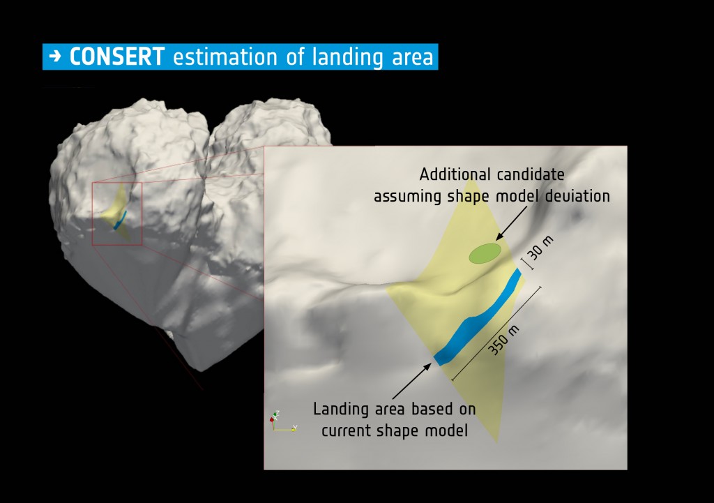
Has anyone heard anything yet from the CONSERT experimenters about their assurance that they would be able to pinpoint the landing site within just a few days after the landing? AFAIK, we haven't gotten that information out here in the non-ESA world yet.
...
-the other Doug (With my shield, not yet upon it)
...
-the other Doug (With my shield, not yet upon it)
There is a recent interview with the PI of CONSERT here (in french) with a lot of details.
QUOTE (Gerald @ Dec 3 2014, 07:15 PM)
It looks rather similar to the mass spectrum of the paper, just with a different scale. Mass 3 may be HD. Could be a mix of H2O, HDO and D2O, decay products, and some impurities like carbon and nitrogen, including simple compounds like NH or CH, CH2, and CH3.
I don't think, that it's pure H2O, with protium the only hydrogen isotope.
@stone: Thanks very much for the links! They give a real feeling of the science team's perspective of the Philae operation.
I don't think, that it's pure H2O, with protium the only hydrogen isotope.
@stone: Thanks very much for the links! They give a real feeling of the science team's perspective of the Philae operation.
The chance that the two plots come from the same raw data is huge, so this is a mixture of D2O and H2O with a little air N2 and O2 so what you see is:
D2O+ = 20
H3O+ = 19
DHO+ = 19
H2O = 18
DO+ = 18
HO+ = 17
O+ = 16
stone
QUOTE (jmknapp @ Dec 3 2014, 09:01 PM)
But the (hypothesized) contact with the ground partway through, not rising to the level of an official bounce, throws a wrinkle in that calculation, if it remains unknown where that contact occurred.
That's absolutely true - that's what I meant by the second bounce. It may be better to just refer to it as "second contact", there being (at my last count) four distinct contacts (each of which may have involved multiple touches of lander parts onto the ground).QUOTE (4th rock from the sun @ Dec 1 2014, 09:12 AM)
You can have clear sky below the horizon if we are up from the surface. On a small world with lots of vertical relief that's possible.
But I think that you can try to tilt the panorama the opposite way, with the NW raised regarding the horizon. To match the sun position you may also need to rotate it horizontally to the left / W , but not by much.
It will still fit the data we have and the light / shadows well. At the same time, the local slopes will be lower.
Something like this (disregard the horizontal positioning):
Click to view attachment
At least it's an alternate possibility that doesn't require extreme slopes.
Interesting to consider the horizon depression. As an example if the radius of curvature is 1km and the relief is 100m (10%), then the horizon dip is 25 degrees. The dark space seems to approach 45 degrees in my recent rendering and one would need more than 400m relief, much more than I can see in this area on the images & shape models.
My take on some of the constraints (e.g. Brian's sun altitude of 28 degrees, along with Malmer's XYZ sun vector) is that the portion of Philae that is tilted up would be one variable, and the amount of needed tilt to match the sun altittude is a function of this. Thus if panel #1 is lifted up then I see a high tilt being needed (similar to an earlier post). If panel #5 is lifted up then a lower tilt would fit.
QUOTE (fredk @ Dec 3 2014, 09:20 PM)
That's absolutely true - that's what I meant by the second bounce. It may be better to just refer to it as "second contact", there being (at my last count) four distinct contacts (each of which may have involved multiple touches of lander parts onto the ground).
No, it was regular bounce, just like every other, because direction of lander movement was significantly changed. Only difference was that lander most likely did not hit the ground with the expected axis, that is, with all three legs towards the ground. It was probably the lender still being vertical, moving sideways, and hitting the crater wall, first with the one, and then with another leg and the body. That is why the pattern of all sensor data change is completely different. The only event that could not qualify as "bounce" would be situation in which lander only slightly grazed the very top of something very high, at the edge of small lobe. After that lander would start tumbling, but it would not significantly change direction of movement. Also, only then it could continue to fly for another 65 minutes without colliding with anything else. However, hitting the very edge of the crater wall with one leg is not only highly unlikely, but in that case lander would continue and go "down", toward the center of gravity and larger boulder for more than one hour. There is no way it could return to the top of small lobe, to the place where Consert data says it is. That is possible only after real bounce "up", away from the center of mass, after full collision with crater wall. We had THREE bounces, not two and "something else we could not name". (ADMIN EDIT: See below)
ADMIN NOTE: Please note that a number of comments above were moved to the 'Junk Drawer' thread as they were off-topic and in some cases, despite comments to the contrary, were criticisms of the science teams approaches to the delivery of their stories and science. It's been a while since we've needed to use the 'junk drawer', so a reminder to all members to help maintain the high signal-to-noise ratio on UMSF to keep discussions 'on-topic'.
I can't find the Twitter post where this appears. Can you give a time and date and anything else that would locate it?
Click to view attachment
QUOTE
The image to which I was referring was this one from the Cosac Twitter. The caption says it is water.Click to view attachment
QUOTE
SETI talk on Dec. 9:
Rosetta: Wild Bounce at comet Churyumov-Gerasimenko
Claudia J. Alexander
Jet Propulsion Laboratory
Also,
Tuesday, December 16 2014 - 7:00 pm, PST
The Rosetta Lander (PHILAE) mission: landing on comet 67P/Churyumov-Gerasimenko
Jens Biele
DLR
Rosetta: Wild Bounce at comet Churyumov-Gerasimenko
Claudia J. Alexander
Jet Propulsion Laboratory
Also,
Tuesday, December 16 2014 - 7:00 pm, PST
The Rosetta Lander (PHILAE) mission: landing on comet 67P/Churyumov-Gerasimenko
Jens Biele
DLR
FYI I got the ESA SPICE data for Rosetta, Philae, and 67P going in Celestia. All the needed data & files are collected into one downloadable .zip file and instructions provided here if you'd like to experiment with that yourself. You just need to install Celestia, one add-on, and then this data on top of it--so pretty simple as these things go.
I took that SPICE data, plus some models I put together in Orbiter for the next two hops, and turned it into this movie that shows exactly what happened to Philae on the initial descent, and then what MIGHT have happened in the next two hops:
https://www.youtube.com/watch?v=xmYiY9SIwkA
The Orbiter modelling isn't really exact (I don't have any way to model the weird clumpy gravity, but I made a rough adjustment by adding 50% to Orbiter's two-body solution of 67P's gravity--based on Brian's comments above on this thread). But it still gives you a decent sense of what is/isn't possible in that kind of microgravity and now that I have sorted out issues with the Orbiter model like rotation direction, speed, axis, size of the comet, etc, it gives answers that are generally in concert with the more sophisticated approaches that we've seen here from Brian & Malmer.
At any rate, my conclusion after messing around with this for quite some time, is that the theory that Philae followed the approximate path outlined in Malmer's video, hit one of the cliffs at the 46 minute point (Malmer has it very near those at exactly the right time, so it is easy to believe), then rebounded to the left and with slightly (about 0.12 m/s) more vertical velocity to land where the Rosetta team thinks Philae is, near the far rim of the crater, is at least plausible.
Screenshot below is from the Celestia animation, based on the SPICE data for the landing.
Three little points, based on thoughts I had while working on the Celestia and Orbiter simulations used to make the movie about Philae's journey across Comet 67P that I mentioned above:
- The area where Philae bounced the first time has about a 15 degree down-slope almost exactly aligned with Philae's path after the bounce. Also the velocity vector of Philae at the moment it hit is aligned very closely with this same path (most of the velocity vector is downwards but the remainder is well aligned with the direction it took after the bounce). And the Rosetta team seems to think the lander would absorb about 2/3 of the vertical velocity if it hit at about 1 m/s.
Those three facts together pretty much explain how Philae ended up going in that exact direction, with a little bit higher horizontal velocity (because of the slope tilted in that direction) and a lot lower vertical velocity (because of the shock absorption of the lander) than it had before the bounce. - The cliff that Malmer shows in his post above, just at the 46 minute mark, would be just about perfect for giving Philae a good bounce to the left at that point (needed to make it arrive at the area where the Rosetta team seems to think it is), and just a very slight upward nudge (needed to make the remainder of the flight last the required amount of time while covering the distance from that point to about where the Rosetta team thinks Philae is).
- If I were a betting man, I'd put my money on Philae somewhere at the bottom of the cliff rather than at the top of the rim. Now it COULD have ended up just about anywhere in that area depending on the exact bounce it took on the 2nd touchdown. Landing somewhere at the bottom of the cliff though, is an easy shot that just about any duffer could make while sleepwalking.
Landing at the TOP of the crater rim, though, is a real hole in one. Just slightly more velocity and it sails right over the top onto the dark side. Slightly less and it hits the side of the cliff. Take a look at the image below from the Rosetta blog post here. The area on top of the crater rim is just a really, really hard spot to hit from the point of the second bounce that we are talking about.
If you were doing a Monte Carlo simulation with slight perturbations of the initial conditions, you'd probably end up with 90% or more of the results at the bottom of the cliff, or maybe even 95% or 99%. I got lots to land at the bottom and lots to fly over the top, but I'm not sure I got even one to land just on the top. It's just a very, very small target.
So, top of the crater is possible, just far less likely . . . if it did end up on top there, I'm definitely going to be saying WOW!
QUOTE (flug @ Dec 9 2014, 01:56 AM)
I took that SPICE data, plus some models I put together in Orbiter for the next two hops, and turned it into this movie that shows exactly what happened to Philae on the initial descent, and then what MIGHT have happened in the next two hops:
https://www.youtube.com/watch?v=xmYiY9SIwkA
https://www.youtube.com/watch?v=xmYiY9SIwkA
That's quite some effort, already!
I think, particularly the sequence from 3:46 - 4:22 regarding rotation, probably even the part after first td can be refined using the Romap data.
After first td Philae's rotation around its z-axis slowly accelerated from almost zero to 1/(13s), due to the flywheel spin-down. Then at 16:30 GMT the rotation abruptly changed to 1/(24s), significantly slower, maybe with an additional torque-free precession. Rotation axis pointing still with a significant contribution of the z-axis.
See also this Rosetta blog post.
I just uploaded another visualization of Philae's journey from Rosetta to 67P. This time it is made with Systems Tool Kit (STK) using the ESA SPICE data:
https://www.youtube.com/watch?v=Yl-U8B5a4Cs...eature=youtu.be
STK has a nice feature that allows you to calculate and display different vectors. So this shows Philae's velocity as it approaches the comet, the direction of Rosetta and the Sun, the direction of the surface rotation vector of 67P at the landing point, etc.
As Brian has mentioned up-thread, STK won't load the SPICE files that hold the attitude & rotation information. That is disappointing, because that data is pretty important. But it does give you better access to the lower level data than Celestia does.
Also FYI the SPICE files still show the trajectory to the planned Philae landing site, which is (if my calculations are correct) about 100-150 meters away from the actual landing site. I jiggered 67P's position just a little so that in this video (and a few I've got forthcoming) Philae's landing site is visually correct as close as I could get it.
QUOTE (flug @ Dec 12 2014, 02:00 AM)
STK won't load the SPICE files that hold the attitude & rotation information.
Nice to see someone else using STK! One way you can get around that limitation is to generate .a files using something like MATLAB after importing the attitude data using the SPICE Tool Kit (they are readable ASCII files and not hard to format). I've already extracted the attitude data into MATLAB and should be able to write it into .a files if you want (or at least .csv files which you could then modify into .a format).
It's too hard to see from the perspective in your video if the comet rotation looks correct, but I was able to set up rotation conditions that match the true rotation state as closely as possible (ie. between the J2000 frame and the ESA model file coordinate system):
Epoch: 12 Nov 2014 15:34:04
Quaternion:
qx = 0.183989
qy = -0.0909598
qz = -0.558697
qs = 0.803574
Body rates:
wx = -0.00306348 deg/sec
wy = 0.00497519 deg/sec
wz = 0.00555866 deg/sec
You also must have converted the .obj file into a .dae file for STK, and somewhere along the lines scaled the model by about 3000x. I apply the scale in STK at the model tab, using a logarithmic scale of 3.425 (about 2661x). This--with the above attitude initial conditions--results in Philae hitting the touchdown location at the right time and spinning with the comet correctly.
The first of the two SETI talks on the landing is now up on youtube:
Rosetta: Wild Bounce at comet Churyumov-Gerasimenko - Claudia Alexander
I had to laugh at this aside from Dr. Alexander:
Next week's talk is from one of the landing engineers, which should be an interesting perspective.
Rosetta: Wild Bounce at comet Churyumov-Gerasimenko - Claudia Alexander
I had to laugh at this aside from Dr. Alexander:
QUOTE
I'm not sure if it's appropriate to talk a little bit now about the midnight message I got right before the landing day--which was that we have problems, umm, and the canister that was supposed to fire and hold the lander down, they weren't sure if it was pressurized properly, and then they weren't sure if maybe the problem was that it was just that the signal that tells them it was pressurized was not being sent properly. So they sent a patch to try to fix that aspect of the software, and the patch didn't work, they didn't test it before they sent it, and so they said, oh oh oh oh, here, we'll do another patch. So they sent the second patch, and then they asked if they could have an extra day and land the next day, and have 24 extra hours to fix it, and evidently the director general of ESA said no, we've got the president of France coming, and we've got all these dignitaries, and you're going. OK, this is hearsay, but it's a great story, I love this story.
Next week's talk is from one of the landing engineers, which should be an interesting perspective.
QUOTE (Brian Lynch @ Dec 12 2014, 03:44 AM)
Nice to see someone else using STK! One way you can get around that limitation is to generate .a files using something like MATLAB after importing the attitude data using the SPICE Tool Kit (they are readable ASCII files and not hard to format).
Thanks for your help an encouragement along the way. I wouldn't have even known the SPICE files existed or were worth looking at without your encouragement. Or that you could use SPICE with these various FREE tools like Celestia and STK. I really appreciate it!
The setup I arrived at in STK (sans attitude data) is very much like what you describe. As you mention, it is pretty easy to tweak the size of the model, put the known rotational axis & speed in, and the confirmation is that Philae comes in & lands just on the (planned) landing site at just the planned landing time, and then 'stick's to the surface for a number of rotations. So if you're surface and rotation rate etc exactly match what ESA predicted for Philae, we know we're at least as close to the real situation as they were in predicting the landing!
The numbers you give there are exactly the ones you need to get 67P's rotation going, so if anyone else wants to give it a try, there you go . . .
For anyone who wants to set up the SPICE data in STK, you just download (free) STK, start a new scenario, create three new satellites in it (Rosetta, Philae, 67P) and load the appropriate SPICE file under 'orbit'.
Those files (currently) are:
LORB_DV_061_01_______00108.BSP
RORB_DV_061_01_______00108.BSP
CORB_DV_061_01_______00108.BSP
Then you can mess around with loading a model for 67P (and/or the spacecraft), getting 67P's rotation set up, and so on.
ftp://ssols01.esac.esa.int/pub/data/SPICE/ROSETTA/kernels/
http://www.agi.com/products/stk/
I could share my current scenario file, 67P model that works in STK etc if anyone would like--it would probably speed things up quite a bit for anyone interested in exploring.
QUOTE (Brian Lynch @ Dec 12 2014, 03:44 AM)
Nice to see someone else using STK! One way you can get around that limitation is to generate .a files using something like MATLAB after importing the attitude data using the SPICE Tool Kit (they are readable ASCII files and not hard to format). I've already extracted the attitude data into MATLAB and should be able to write it into .a files if you want (or at least .csv files which you could then modify into .a format).
This sounded 'easy' so I went ahead & got SPICE files going in MATLAB, too, and started messing around with pulling the attitude data in & exporting it for use STK.
This process was, to put in mildly, extremely fraught. Like at every step there are several choices, all complicated, some undocumented, and I'm pretty sure I made every single wrong one before stumbling on the one that finally worked.
What I'm wondering is, if it wouldn't be worthwhile to set up a SPICE forum here on UnmannedSpaceFlight.com, where people could help each other over all of these very difficult hurdles?
There is a lot of documentation out there for SPICE, but a lot of it is quite technical and putting it together with all the various toolkits it interfaces with, there are just a lot of issues. Plus, each mission has its own unique kernel file with their own unique quirks--much of that is undocumented or, even if documented, not that easy for an outsider to make sense of.
There doesn't seem to be any place online where people are talking about using the SPICE toolkit, kernel files, answering various questions to help newbies, etc.
Might be worth doing?
At any rate, here are a few of the preliminary graphics I made with the SPICE attitude data.
1. Rosetta Orbat wrt to 67P August throught mid-November. You can clearly see the famous 'triangle orbits'
2. Rosetta attitude Nov 12
3. Rosetta attitude Nov 10-13
What's interesting about the attitude files is you can very clearly see when Rosetta is scanning (systematically photographing the surface or whatever, I would assume--the little search grid patterns) vs generally orbiting, communicating with Earth, etc.
QUOTE (flug @ Dec 15 2014, 04:18 AM)
This process was, to put in mildly, extremely fraught... What I'm wondering is, if it wouldn't be worthwhile to set up a SPICE forum here on UnmannedSpaceFlight.com, where people could help each other over all of these very difficult hurdles?
The idea of a SPICE forum has been floated a couple of times and is probably worthwhile, but should respect the UMSF rules that ensure a high SNR -- ie. is this really an appropriate place for a SPICE forum, or should one of us start an external site at Wikia or something?
In the Celestia simulation of the Philae landing using the SPICE data, I calibrated Philae's orientation to Rosetta at the moment it was launched. If you keep that same orientation on down to the surface, Philae arrives in the correct configuration for landing--so I'm taking that as evidence that is indeed Philae's attitude between the time of launch and landing.
So . . . I got thinking, with that bit of attitude information plus the SPICE data, it would be possible to use Celestia duplicate the photos ESA released from just before and after the landing and see if the actual photos match the attitude of Philae in our simulation.
That will confirm our simulations to some degree, but I think it also sheds some light about what happened to Philae at and just after landing--including solving one 'mystery' mentioned by Dr. Alexander in her recent talk about the Rosetta mission.
The relevant photos & simulation screengrabs are attached.
Here are a few comments:
Technical note: When I talk about Philae's 'attitude' above I mean the general attitude of the lander and spin axis, but NOT the exact spin rotation at any given moment.
We know the approximate rate of spin for Philae during this segment of the flight, but we won't have any specific attitude data for the spin angle at any given moment. In my simulations I've just set the spin rate to 1 rev/minute and left it at that. For the photos below I've chosen a moment nearest the minute the photo was taken that matches the spin angle, just because that makes it easier to compare the remaining attitude angles at those moments. But don't go home thinking, "gosh, that's an amazing simulation--it matches the EXACT spin rotation down to the millisecond!"
So . . . I got thinking, with that bit of attitude information plus the SPICE data, it would be possible to use Celestia duplicate the photos ESA released from just before and after the landing and see if the actual photos match the attitude of Philae in our simulation.
That will confirm our simulations to some degree, but I think it also sheds some light about what happened to Philae at and just after landing--including solving one 'mystery' mentioned by Dr. Alexander in her recent talk about the Rosetta mission.
The relevant photos & simulation screengrabs are attached.
Here are a few comments:
- 15:14 (compare the 15:14 inset to philae-15-14.jpg): The attitude does match very well to my eye.
- 15:19 (philae-15-19.jpg): Again, appears to be a good match
- 15:23 (philae-15_23.jpg): Again, a good match
- 15:33 (philae-15_33.jpg): In the SETI talk yesterday, Dr. Alexander mentioned that the ESA staff believe that the three 'pits' shown in the 'touchdown point' inset are not indentations created by the lander feet. Reason: The distances between the pits are bigger than the dimensions of the lander feet, so they don't fit. One or more of them must be a shadow or image of the lander, or something else.
Based on these photos & simulations, I think we can offer an explanation for the three marks. Philae came in with a velocity vector at a significant angle to surface normal (see diagram philae-67P-landing-surface&vectors.png, generated with STK). That angle looks to me to be 20-25 degrees.
Philae's velocity vector is (approximately) aligned with Philae's spin axis.
So Philae came in in the approximate configuration I've shown in philae-15_33.jpg, with the velocity at that angle to the surface and the lander also titled at approximately that angle.
With this angle to the surface, the left-most two feet plow through the dust and hit the surface first, leaving the two divits you see on the left. These two divits are at about the correct distance for the left two legs (compare with simulator screencap philae-15_33.jpg).
These two legs hit and rebounded and then (because of the angle to the surface) the right leg hit at a slightly later time and so left its mark somewhat to the right of the spot you would expect if all three legs hit simultaneously. That pretty well explains the configuration of the 3 marks. - 15:43 (philae-15_43.jpg): The jpg shows the configuration Philae would have had at this moment if it hadn't hit something and been disturbed in its orientation and spin. Obviously, it HAS hit something and its spin is now quite different than it was previously.
- philae-67P-landing-surface&vectors: This shows a number of interesting vectors (courtesy STK) but the one I wanted to point out here is Philae's velocity vector relative to the surface. Here the velocity vector is shown directed straight down and the surface is oriented to that.
Basically, on earth this would be as thought Philae landed straight down on a hillside with 20-25 degree slope.
If Philae's velocity had been normal to the surface (ie, 100% vertical) then presumably it would have bounced straight back up (at a lower rate of speed because of the damping in Philae's landing gear). But since it has a very considerable 'horizontal' component to its velocity before the impact, it had probably very close to the same horizontal velocity afterwards as well.
I'm guessing you could model the Philae impact pretty well as damped by about 2/3 in the vertical direction (which is about what the Rosetta team seems to think) but just a straight-up elastic collision in horizontal.
If you look at the clues we have to Philae's horizontal velocity right before & after landing, it doesn't seem to deviate much, if at all--same direction, same magnitude.
We sort of imagine Philae as just coming straight down and bouncing straight up, but this diagram shows it came in with some considerable horizontal velocity--meaning that it likely left with nearly the same horizontal velocity. That's what all the other evidence seems to suggest, as well.
Technical note: When I talk about Philae's 'attitude' above I mean the general attitude of the lander and spin axis, but NOT the exact spin rotation at any given moment.
We know the approximate rate of spin for Philae during this segment of the flight, but we won't have any specific attitude data for the spin angle at any given moment. In my simulations I've just set the spin rate to 1 rev/minute and left it at that. For the photos below I've chosen a moment nearest the minute the photo was taken that matches the spin angle, just because that makes it easier to compare the remaining attitude angles at those moments. But don't go home thinking, "gosh, that's an amazing simulation--it matches the EXACT spin rotation down to the millisecond!"
Couple of people asked about how to get started modelling Rosetta/67P in STK. Here is the quick rundown:
1. Download STK - the free version should do everything you need to:
http://www.agi.com/products/stk/
2. Make a new scenario
3. Add 3 satellites, 67P, Rosetta, & Philae. General instructions here:
http://help.agi.com/stk/10.1.3/index.html?...tk%2Fauthor.htm
4. For the orbit of each satellite, use SPICE files. General instructions here:
http://help.agi.com/stk/10.1.3/index.html?...tProp_SPICE.htm
5.You can download the needed SPICE files here in directory spk:
ftp://ssols01.esac.esa.int/pub/data/SPICE/ROSETTA/kernels/
These are the files you need (names are as of 12/16/2014 - they are updated often and you will want the most recent of the similarly named ones):
RORB_DV_064_01_______00115.BSP (Rosetta)
LORB_DV_064_01_______00115.BSP (Lander)
CORB_DV_064_01_______00115.BSP (Comet)
There is a bunch of diddling around with setting the dates when the files are active; main problem is insuring your chosen dates are actually covered by data in the file. The *ORB files contain a number of time segments & you can view info about them within the 'orbit' settings screen once you have loaded the file.
8. Getting models in the right format. The main problem is getting the model into either MDL or DAE format, the only formats STK uses. Instructions here: http://www.agi.com/resources/faq-system/fa...s.aspx?id=11134. Another options: Some programs, ie Blender (open source), will save or convert to DAE (Collada) format.
I've uploaded two versions of the ESA 67P model, that work with STK, to this zipfile:
http://brenthugh.com/celestia/67p-STK-models.zip
7. Adding a model. In your satellites' 'property' screen you can load a model in 3D Graphics/Model, size it correctly ("log scale" for 67P is about 3.433 give or take--once you have Philae's orbit loaded you can view 67P just after landing to see Philae's position & set 67Ps size so that Philae is just on the surface).
8. Orienting the model correctly. Most models will need something like +/-90 or 180 degree rotations about X, Y, and/or Z axes in order to be oriented correctly in STK. Every single graphics package seems to have a different convention as to whether X, Y, or Z is the primary axis. Whatever model you have in whatever system, you can orient the model correctly using 3D Graphics/Offsets.
9. Now you have to set the orientation & spin for each satellite in Basic/Attitude. This is where STK falls down as it doesn't load SPICE attitude data. But Brian Lynch gave the basic info you need to get spin going for 67P here: http://www.unmannedspaceflight.com/index.p...st&p=216247
If you want to mess around with the SPICE data for attitudes/spin for 67P & Rosetta, I've uploaded a couple of sample files here that cover certain periods right around the Philae landing. No guarantee they are correct; I've noticed some discrepancies I can't explain!
http://brenthugh.com/celestia/67p-rosetta-...files-draft.zip
That's just scratching the surface--there are LOTS of buttons to twiddle with!
Interesting to see these Celestia simulations and STK tutorial. I wonder if it is possible to do the Celestia views with Malmer's shape model, and possibly with Rosetta images draped over them? Same thought with the gravity simulations. I'll resume my seat in the peanut gallery.
QUOTE (flug @ Dec 15 2014, 11:09 PM)
In the SETI talk yesterday, Dr. Alexander mentioned that the ESA staff believe that the three 'pits' shown in the 'touchdown point' inset are not indentations created by the lander feet. Reason: The distances between the pits are bigger than the dimensions of the lander feet, so they don't fit. One or more of them must be a shadow or image of the lander, or something else.
When she answers a question, she seems to be talking about the navcam image that shows the lander and its shadow (she refers to the "hole" and bright and dark spots earlier). She doesn't make any clear statement about the contacts visible in the OSIRIS post-first-bounce frame.
We've talked about these contacts before - there are actually four, not three. Check out the posts starting around this one.
Three crops of screenshots of today's AGU Rosetta press conference:
Click to view attachment
The first is an image taken after the first bounce, today published for the first time; the other two are stretched versions of the CIVA1 Panorama 1 image.
Click to view attachment
The first is an image taken after the first bounce, today published for the first time; the other two are stretched versions of the CIVA1 Panorama 1 image.
NASA has put up images from the press conference here.
Click to view attachment
Click to view attachment
Looks like some rocks are visible in the motion-blurred CIVA picture?
Click to view attachment
Click to view attachment
Looks like some rocks are visible in the motion-blurred CIVA picture?
The image at the bottom of your link shows a view of the lander's orientation that I don't think has been seen before, too. Philae is certainly on its side...
Jonathan Amos @BBCAmos 4m4 minutes ago
Sierks: Images now of pits venting. Jets of gas & dust. One image looks right inside. Bobbled surface, like "dinosaur eggs" #agu14 #rosetta
Rebecca Morelle @rebeccamorelle 4m4 minutes ago
Looking into a pit now - we see a 2-3m pebbles down in the hole - Sierks: what on earth are they? #AGU14 #Rosetta
Jonathan Amos @BBCAmos 7m7 minutes ago
Sierks now showing cliffs that look as though they will collapse any moment. Big cracks #rosetta #agu14
Sigh and this is the image news agencies have to lead with Philae comet landing 'all a blur' Yep, thats really going to get people excited about Rosetta again.
QUOTE (Explorer1 @ Dec 17 2014, 06:43 PM)
The image at the bottom of your link shows a view of the lander's orientation that I don't think has been seen before, too. Philae is certainly on its side...
This puts the orientation of the CIVA mosaic back to something close to the following:
Click to view attachment
Green dots left to right are direction of panels #2, #6, #1. Yellow is sun in early afternoon. North is in center of diurnal arc. Philae tilt is set at 80 degrees with panel #1 aiming the highest. I'm unsure what the red/green lines are in the press release. If it's directional information we can see if it is consistent.
The link in xflare's post mentions glare marks so that could help with determining sun and Philae orientation, if we knew which lander parts were reflecting the sun. I'll have to see if it's possible to add reflection points of the panels into the rendering.
QUOTE (scalbers @ Dec 17 2014, 07:29 PM)
The link in xflare's post mentions glare marks so that could help with determining sun and Philae orientation, if we knew which lander parts were reflecting the sun. I'll have to see if it's possible to add reflection points of the panels into the rendering.
The slide presenting the "cliff" image with glare mentions that this is coming from Philae's feet.
https://twitter.com/rebeccamorelle/status/5...1375872/photo/1
QUOTE (Explorer1 @ Dec 17 2014, 07:43 PM)
The image at the bottom of your link shows a view of the lander's orientation that I don't think has been seen before, too. Philae is certainly on its side...
It's worth stressing that the landscape in that rendering is an artist's conception, rather than based on actual images. They still don't know for sure where the lander is. It's also not clear how well they know the orientation. Eg, have actual calculations based on power received on each panel been used, like people have been trying to do here qualitatively?
This is a "lo-fi" version of our main content. To view the full version with more information, formatting and images, please click here.