Perhaps some purer ice got ejected from somewhere else on the comet?
I wonder if anyone here has seen the 10 meter wide region mentioned at AGU from the new CONSERT data reduction. Where does this lie relative to the "Philae Glint"?
Full Version: Philae landing on the nucleus of Comet 67P C-G
Pages: 1, 2, 3, 4, 5, 6, 7, 8, 9, 10, 11, 12, 13, 14, 15, 16, 17, 18, 19, 20, 21, 22, 23, 24, 25, 26, 27, 28, 29
QUOTE (Malmer @ Dec 22 2014, 03:15 PM) 
I wonder why some boulders are so much brighter than the surroundings.
IIRC they mentioned an albedo of 0.13 (?) beneath Philae's (preliminarily) final landing site. The mean albedo of the nucleus is somewhere near 0.04.
Reflectance is dependent of surface roughness and angles (BRDF).
Besides this, chemical composition of the surface varies.
QUOTE (scalbers @ Dec 22 2014, 05:28 PM)
I wonder if anyone here has seen the 10 meter wide region mentioned at AGU from the new CONSERT data reduction. Where does this lie relative to the "Philae Glint"?
Is this the region you mean? The figure is cropped from the snapshot of an AGU presentation posted by Deepnet (#1051). The 2nd frame from Malmer's glint gif is included for comparison.
QUOTE (flug @ Dec 22 2014, 05:45 PM)
I wonder why it is so much brighter than the surroundings, and from seemingly a bunch of different angles as well?
It may be smooth while everything else is rough.
QUOTE (Malmer @ Dec 22 2014, 09:15 AM)
The Glint is not Philae. After looking more carefully. (I wish i had done that before posting)
You're in good company, Dr. Claudia Alexander said in her SETI Talk on Dec. 9th:
QUOTE
Now we don't know exactly where Philae is located now, although last week they showed us some delightful photographs, about a half a dozen photographs, where people have gone in and tried to find it and have seen this tripod-like figure and said, "there it is!" And they're all over, they're all over the surface. "I found it!--and it's over here." "No, no, I found it and it's over here." So we still don't know where it is.
IMHO Malmer's glint is inside the AGU CONSERT location. Has the area changed since landing ? A difficult call given the data available. If Philae is not exactly there it may be only metres away, the glint could be a fresh shear, Philae appears to have knocked a chunk clear out of where it has landed, perhaps that glints also ?
http://www.bbc.co.uk/iplayer/episode/b04vk...ars-of-creation
BBC Sky at night discuss Malmers CIVA depth image at 27 minutes in.
If OSIRIS doesn't announce soon is that evidence of abscence ?
Holger Sierks seemed to say it would be hours / days at the press conference at the start of AGU at 45m10s - he was awaiting 3 sunlit OSIRIS sweeps of the area downloading.
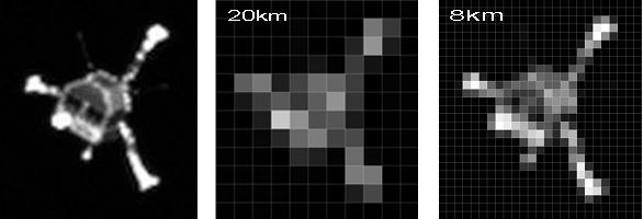
What surface resolution has OSIRIS at 20Km ?
http://www.bbc.co.uk/iplayer/episode/b04vk...ars-of-creation
BBC Sky at night discuss Malmers CIVA depth image at 27 minutes in.
If OSIRIS doesn't announce soon is that evidence of abscence ?
Holger Sierks seemed to say it would be hours / days at the press conference at the start of AGU at 45m10s - he was awaiting 3 sunlit OSIRIS sweeps of the area downloading.
What surface resolution has OSIRIS at 20Km ?
QUOTE (Brian Lynch @ Dec 21 2014, 05:43 PM)
- Can you share your coordinates for the three impact points in the ESA model frame (unscaled)?
OK, here are the coordinates of the three impact points as reported by STK in two different frames (body rotating & inertial). This is what STK will easily spit out (so not exactly what you asked for, I know).
Note that I'm now using a slightly tweaked version of Malmer's model--jiggered the axes etc until it fit the ESA model as best I could make it. Then I've also rube-goldberged the rotation just a bit so that the SPICE landing scenario lands on the actual (rather than planned) landing spot.
All that is to say this may or may not line up with anything in your model if it doesn't have my special rube-goldbergian modifications.
All points are given as [x,y,z].
67P Body Fixed Frame (Rotating)
Landing point
[x,y,z]=[ 2.13549 km, -0.941758 km, 0.494823 km]
Second impact (side of Mount Malmer)
[2.45225 km, -0.647386 km, -0.0960692 km]
Third impact (near the Glint)
[2.5601 km, 0.239315 km, 0.437063 km]
67P ICR Frame (Inertial)
Landing point
[1.11719 km, -1.53962 km, -1.43998 km]
Second impact (side of Mount Malmer)
[-0.267386 km, -1.73915 km, -1.82913 km]
Third impact (near the Glint)
[-1.64107 km, 0.0760335 km, -2.02572 km]
QUOTE (Deepnet @ Dec 22 2014, 11:18 PM)
What surface resolution has OSIRIS at 20Km ?
CODE
parameter NAC WAC
-----------------------------------------------------------------
Focal Length, mm 700.0 140
f/ratio f/8 f/5.6
IFOV, rad/pixel 0.0000188 0.0000993
Field of view (deg)
Cross-track 2.35 12.0
Along-track 2.35 12.0
So at 20km, NAC pixels are 0.0000188*20000 = 0.38 m and WAC pixels are 0.0000993*20000 = 1.99 m
They said at AGU that they plan a flyby at 8km (after the "bound orbit" phase ends) but is that in connection with trying to image Philae per se? So maybe it would look something like this:
Eyeballing the location of the 'blue triangle' from the CONSERT data posted by Deepnet & Brian above onto a photo, I get something roughly like the blue triangle in my graphic below. CONSERT graphic also attached, for easy comparison.
If that location is accurate, and our 'three bounce' theory of Philae's flight across the head of 67P is anything like correct, I'm going to go out on a limb and say that Philae couldn't have flown directly from Mount Malmer to the blue triangle, which is over the edge from the perspective of Mount Malmer. Luckily we know there was a few minutes flight time between 3rd & 4th impact--and that is what could have taken it over the edge.
My thoughts: 3rd impact must have been more on top, somewhere like the spots I've indicated with the pink dots in the graphic. Most likely (?) one of the pink dots nearest the blue triangle. Those are the general types of landing areas available on that type of trajectory. Philae must have, by chance, landed more or less on its feet, allowing much of its velocity to be damped. With that velocity damping, depending on the specifics, it could have flown say 50-200 meters more (going just about any direction, depending on the specifics of what it hit) in the time frame of the 3rd to 4th bounce, ending up in the blue triangle. It's also possibly pure luck that it landed in something of a cleft, and perhaps it bounced around a bit more within the cleft, eating up more of its momentum before arriving at its very final position.
Also I'll hazard that it if anything like that scenario is true, was pure chance/luck that the flight ended there. It could easily have taken another bounce similar to the one it took at Mt Malmer, leaving it with nearly the same velocity it arrived with and flown on, say, all the way down to the bottom of the neck, or any number of other locations . . .
Additionally, if it's at the bottom of the rather deep-looking cleft near the center of the blue triangle, it may take a rather particularly advantageous angle of both the sun and Rosetta to see any glint from Philae. That could be the reason Philae hasn't been spotted yet.
UPDATED TO THIS COMMENT 9 JAN 2015: Actually, Philae could have traveled pretty directly to its final resting spot if it is in the blue triangle. When I wrote the above I thought Philae was coming across the middle of the crater to this location. But it turns out Philae's path is likely/pretty certainly more along the ridgeline to the left or even left of the ridgeline. So it could have flown directly to points right in the blue triangle.
jmknapp - thanks those scaled Philae images are handy.
1st Touchdown was measured by SESAME-CASSE and Knapmeyer's AGU paper presentation talks about it in detail.
CASSE is a piezo accelerometer in each sole (2 per foot, 6 in all) range 0.0054 to 230 ms^-2, 4 - 16Khz sample rate.
https://virtualoptions.agu.org/media/P34B-0...eyer/0_qz0krayj
(free AGU membership required to view video)
Click to view attachment
From 2 minutes into the presentation : "
...at the 1st dip here, at zero, this is taken as a trigger signal because it's a ring buffer also the .2 seconds before this are kept in the memory. The signal flattens out after about a second or so, a second and a half and this probably means that the lander is already flying then.
The time difference between the 1st signal, the 1st really touching the ground, which is [*audience cough*] the trigger signal, the main pulse is 200ms and we interpret it as about 20cm of soft material, dust, above more solid stuff. 20cm, the velocity of the lander at this point is 1m/s to a good approximation.
The main pulse on the +Y foot is not just one, it is a bit dragged out, the interpretation is that the foot is either pushing through in-homogenous material or it is dragging a bit over a rough surface so it getting multiple oscillations until finally the pulse dies out, sliding or ploughing...
The Young's Modulus of the solid material exceeds 0.4MPa. "
, and concludes about the final site,
"The data from the MUPUS hammering indicates that all 3 feet are in contact with the surface, we do not believe that one of the feet is just pointing into the sky."
QUOTE (jmknapp @ Dec 23 2014, 10:33 AM)
They said at AGU that they plan a flyby at 8km (after the "bound orbit" phase ends) but is that in connection with trying to image Philae per se?
The planned flyby at 6 km above the surface / 8 km from center next February has been planned considerably before they even dropped Philae. It's part of Rosetta's regular science mission, iirc to sample the inner coma closer to the surface.
Click to view attachment
The CONSERT sites in cross-eye-stereo from ROLIS descent
The CONSERT sites in cross-eye-stereo from ROLIS descent
QUOTE (Deepnet @ Dec 23 2014, 11:58 AM)
"The Young's Modulus of the solid material exceeds 0.4MPa. "
Wow, that is about the stiffness of very soft mud or a stale marshmallow.
QUOTE (Brian Lynch @ Dec 23 2014, 04:48 PM)
Wow, that is about the stiffness of very soft mud or a stale marshmallow.
They likened it to crème brûlée (with a bit of a crust). Also, see this video starting at about 35:30.
Then again, they said the same thing about Titan re the Huygens landing, so maybe it's all crème brûlée all the way down.
Joe
Interesting, I hadn't realized Huygens experienced a similarly "squishy" landing. Given the atmosphere and presence of liquid methane, I can see how that kind of surface could exist there. It is hard to imagine the same thing on a comet nucleus (there aren't any liquid components, right?). So does that suggest the material is extremely porous? Maybe something like very light snow that compacts easily under foot?
Could you edit or re-post the second link (it is the same as the first one).
QUOTE (jmknapp @ Dec 23 2014, 06:24 PM)
Also, see this video starting at about 35:00.
Could you edit or re-post the second link (it is the same as the first one).
Oops, sorry:
https://www.youtube.com/watch?v=kW4t-8v13aQ (fixed in the original)
Starting around 35:30 she talks about typical megapascal values for crème brûlée and snowballs-good to know.
https://www.youtube.com/watch?v=kW4t-8v13aQ (fixed in the original)
Starting around 35:30 she talks about typical megapascal values for crème brûlée and snowballs-good to know.
QUOTE (Brian Lynch @ Dec 24 2014, 05:21 AM)
So does that suggest the material is extremely porous? Maybe something like very light snow that compacts easily under foot?
Processed first bounce image seems like a snow with Philae's footsteps, doesn't it?
I'm going to go out on a limb and say "no."
It looks like just noise to me (though I am sure some real features are present, it's not clear to me how to identify them in that image).
It looks like just noise to me (though I am sure some real features are present, it's not clear to me how to identify them in that image).
QUOTE (Hungry4info @ Dec 24 2014, 05:26 PM)
I'm going to go out on a limb and say "no."
It looks like just noise to me (though I am sure some real features are present, it's not clear to me how to identify them in that image).
It looks like just noise to me (though I am sure some real features are present, it's not clear to me how to identify them in that image).
It's possible that there're artifacts of processing - the applied method is very strong in details extraction and it can enhance noise.
But in my interpretation:
1. Camera looks down with some perspective at the left, and closest surface at the right looks like a snowdrift
2. There're consistent shadows from light source directed from the top of the image.
3. Supposed "footsteps" have some kind of symmetry (yellow), and some elements seem too sharp for processed noise (red).
Click to view attachment
Of course it may be artifacts of processing and imagination.
 But I think there're some chances that image is true. It would be a pity to throw them away.
Another attempt at sharpening looks quite different, which suggests many details are noise/deconvolution artifacts.
We also haven't heard when this CIVA image was taken. It was pre-planned to go after landing - does anyone know how long after landing? If it was many minutes then we likely couldn't see the first bounce spot (at least any better than we already have with OSIRIS).
I've been puzzled by the look of this image - why does it have a "square wave" bottom edge? There's no sign that this is a mosaic of separate CIVA-P frames. My best guess is that we're seeing a single frame, but some of the data was lost due to imperfect communication while the lander was between bounces.
I made a new simulation of "Philae's Wild Ride" across the head of 67P--this time I got Malmer's 3D model going, which makes an amazing difference as far as seeing detail and jus the overall look.
https://www.youtube.com/watch?v=6GCrlWhqLBU
One view (frame shown below) is from Rosetta's perspective.
https://www.youtube.com/watch?v=6GCrlWhqLBU
One view (frame shown below) is from Rosetta's perspective.
QUOTE (fredk @ Dec 24 2014, 08:18 PM)
Another attempt at sharpening looks quite different, which suggests many details are noise/deconvolution artifacts.
They completely match.
Click to view attachment
(animation)
QUOTE (fredk @ Dec 24 2014, 04:18 PM)
[url="http://www.unmannedspaceflight.com/index.php?s=&showtopic=7896&view=findpost&p=216419"]
We also haven't heard when this CIVA image was taken. It was pre-planned to go after landing - does anyone know how long after landing?
We also haven't heard when this CIVA image was taken. It was pre-planned to go after landing - does anyone know how long after landing?
My source told me 5 minutes
QUOTE (fredk @ Dec 24 2014, 04:18 PM)
I've been puzzled by the look of this image - why does it have a "square wave" bottom edge? There's no sign that this is a mosaic of separate CIVA-P frames. My best guess is that we're seeing a single frame, but some of the data was lost due to imperfect communication while the lander was between bounces.
IIRC the day after landing it was reported that the first sequence of post-landing images had been spoiled by stripes and black areas
QUOTE (flug @ Dec 24 2014, 04:48 PM)
I made a new simulation of "Philae's Wild Ride" across the head of 67P--this time I got Malmer's 3D model going, which makes an amazing difference as far as seeing detail and jus the overall look.
https://www.youtube.com/watch?v=6GCrlWhqLBU
One view (frame shown below) is from Rosetta's perspective.
https://www.youtube.com/watch?v=6GCrlWhqLBU
One view (frame shown below) is from Rosetta's perspective.
me like!
QUOTE (Paolo @ Dec 25 2014, 12:18 AM)
IIRC the day after landing it was reported that the first sequence of post-landing images had been spoiled by stripes and black areas
Given the fact that Philae was moving, I would guess the CIVA image will be very badly smeared with motion blur.
From what I understand CIVA is not a line-scanning camera (like f.i. the Viking camera's were) but it will have used a very long exposure time given the expected low-light conditions. When the picture was taken the craft was moving across the surface and, even more importantly, it was spinning. But by the looks of it the movement wasn't (yet) chaotic, it wasn't tumbling at that time, just spinning across it's vertical axis.
So if we know the spin-frequency at the time, won't it be possible to calculate the angle the CIVA camera turned during the time it took to take this picture? That would at least give direction and length of motion blurr for each pixel due to the spinning (provided the spin wasn't too fast, if Philae made more then one complete turn during the exposure time I guess you can forget it). Once you know direction and length of motion blurr you might be able to compensate for it by re-calculating the brightness of each separate pixel as the integration of pixels across that vector.
A second blurr will be caused by the motion of Philae itself across the surface, and this will be more difficult to calculate (even if we have an approximation of speed, height and direction of the craft) as it will depend on the distance of each pixel on the imagined landscape but given the fact that we know the angle CIVA is looking in (slightly down) we might work it out at least for a 'flat' surface (objects near the horizon will move less then objects almost directly underneath).
It's a hell of a lot of mathematics and lots of assumptions but I guess it's the only way to get at least something out of that image.
The ROMAP data, from Did Philae graze a crater rim during its first bounce? ,shows Philae's rotation from 15:50.
The blog post gives the following interpretations : A rotation period of 8.5 minutes unchanged during final descent; changes to a period of 13 seconds after the 40 minute flywheel spindown which corresponds with the ROMAP graph at 16:10. At 16.10 : "after that the lander was tumbling. We did not see a simple rotation about the lander’s z-axis anymore,".
As the graph is linear it seems that ~5 minutes after Philae's 1st 15.34 touchdown, Philae's rotation rate would be ~0.02Hz, a ~50 second rotation period.Click to view attachment
QUOTE (jmknapp @ Dec 23 2014, 07:44 PM)
Starting around 35:30 she talks about typical megapascal values for crème brûlée and snowballs-good to know.
Ha, penetrometry is not that big a field, but funny that crème brulee is now the standard analog for mechanical properties of exotic planetary surfaces.
You can hear the origins of that meme just over 40 minutes in at
https://www.youtube.com/watch?v=cgyWaoaIW3Q
Crème brulee or not, the penetrometer strength at Titan was about 0.3 MPa, with the 'crust' (more likely a cobble) reading 2-3 times that.
QUOTE (rlorenz @ Dec 27 2014, 01:33 PM)
Crème brulee or not, the penetrometer strength at Titan was about 0.3 MPa, with the 'crust' (more likely a cobble) reading 2-3 times that.
That is a great talk, thanks! Interesting how the meme started from this and after going through the explanation you end up saying it was more likely a cobble. (Also wish my thesis had 0.05 seconds of data from an instrument I sent to Titan!)
I've been working on adding textures to Malmer's 3D model, to give yet more detailed views of Philae's flight across the head of 67P.
You can take a look here--Philae's ride across 67P with 3D model & photorealistic textures from the ESA navcam images:
http://youtu.be/uzm753E2iKE
I think the photorealistic textures really add something. You can really locate where you are on the comet and the details help put things in perspective.
Just for example, it surprised me how TALL the cliffs were, how DEEP the craters, and so on. Philae really traveled across a fantastic landscape!
QUOTE (Paolo @ Dec 24 2014, 09:18 AM)
IIRC the day after landing it was reported that the first sequence of post-landing images had been spoiled by stripes and black areas
QUOTE (Geert @ Dec 27 2014, 02:55 AM)
Given the fact that Philae was moving, I would guess the CIVA image will be very badly smeared with motion blur.
The images being "spoiled" was what we were told in the media room in the day after landing. But when Bibring gave his talk at AGU, he made it sound as if it was clear from the CIVA images from the beginning that they were taken while the spacecraft was in motion; that they knew they were taken in the middle of a bounce, and knew from the ROMAP data that they had relaunched from the surface. Moreover, he talked of worry that the spacecraft had bounced with more than the escape velocity, meaning it would never return to land. It makes me wonder whether everyone knew they were bouncing, or not. Part of the reason for all the confusion in Darmstadt was that Philae was not operated from there; we weren't getting information straight from mission operators, only secondhand and by word of mouth through their counterparts at ESA.
QUOTE (flug @ Dec 29 2014, 05:39 PM)
I've been working on adding textures to Malmer's 3D model, to give yet more detailed views of Philae's flight across the head of 67P.
That is beautiful, I tried adding some texture to a .dae file but STK rendered it with some weird transparency effects. Any chance you are willing to share your STK model file?
Here are a couple of interesting (to me!) insights from looking at the 3D models & various photos of 67P.
The SPICE data from Philae has the surface rotation vector of 67P. It's about 0.33 m/s in the direction shown by the blue arrow in the photos below. That's not huge (about 0.74 mph or 1.2 km/hr) but it's always from the same direction and continuous.
It amounts to a continuous .74mph/1.2kph 'wind' in the opposite direction of surface rotation. I would imagine that when the comet is active, this 'wind' is very active as well, despite the lack of permanent atmosphere.
Looking at the photos of the head, it's interesting that:
- Nearly all the dunes line up perpendicular to the direction of rotation.
I assume this is similar to the way dunes on earth line up perpendicular to the direction of the prevailing wind, and perhaps the reasons are somewhat similar. - The dust/smaller particles in the crater appear to be mostly piled up on the 'downwind' side; the upwind side has larger boulders etc but a distinct lack of smaller dust. In fact the entire downwind side of the large crater has a 'dust slope' leading up almost to the top of the cliffs there. Is that entire area filled with dust, or perhaps larger rocks underneath, covered with dust?
By contrast, the opposite side of the crater (upwind) is dominated by large rockfalls with little dust.
The photo of the crater (attached) has the comet rotation coming straight towards you (note blue arrow) so you can imagine the 'wind' blowing from straight behind you towards the far side of the crater.
Another perspective showing the dunes perpendicular to rotation direction. Here the 67P rotation direction is directly away from the viewpoint, so you can imagine the wind blowing straight into your face.
Here you can see several smaller craters--and also that they appear to be filled with dust more on the upwind than the downwind side, as the large crater is. So the 'downwind dust' theory might need some more work.
Here you can see several smaller craters--and also that they appear to be filled with dust more on the upwind than the downwind side, as the large crater is. So the 'downwind dust' theory might need some more work.
QUOTE (Brian Lynch @ Dec 29 2014, 05:38 PM)
That is beautiful, I tried adding some texture to a .dae file but STK rendered it with some weird transparency effects. Any chance you are willing to share your STK model file?
Yes, I had a lot of trouble with that kind of thing as well. I think I tried about every POSSIBLE combination of programs to create the meshes & textures and convert them between different needed file formats. (Where's the little icon of me pulling my hair out all over the floor while I was trying to get this to work . . . many perfectly beautiful looking textures in Meshlab that just didn't work in STK or Celestia, no matter what.)
FYI I **think** the transparency effect is just because the UV map is messed up. I've got this working now with .dae file in STK made a certain way, but the the exact same mesh/texture converted to .mdl (STK) or .3ds (needed for Celestia and Orbiter) results in deformed meshes. I **think** the reason is the UV map gets messed up in some way. Also, I couldn't get .dae files created by Meshlab or Blender to open up in STK at all.
Here is the procedure I came up with:
- Meshlab: Open mesh; open images as 'rasters'
- Shift-R to view a raster; then manipulate the mesh to line it up visibly with the features on the mesh. Filters/camera/Image alignment: Mutual information can help (at times)
- Once you've got all you rasters line up, filters/texture/parameterization + texturing from registered rasters AND/OR project active rasters color to mesh, filling the texture
- You have to experiment with different settings in those tools to get the results you want.
- Export from Meshlab to .obj format
- Use the converter at http://www.greentoken.de/onlineconv/ to convert the .obj (and associated .obj.mtl file) to .dae (Collada) format
- That .dae file should work in STK. A direct export from meshlab to .dae doesn't seem to work, and converting the .obj to .lwo to STK's native .mdl format doesn't work, either. The UV map get messed up.
- The .dae from greentoken.de is super bright for some reason. I had to go in and turn down all the various lighting levels to avoid being blinded. There is probably some way to adjust this by editing the .dae file.
I'll upload my current version of the mesh & texture file as well, as soon as I can get it packaged up.
Regarding the dunes: my guess would be that they are wrinkles caused by buckling whenever the rotation speed decreases.
The paper by Mottola et al. (2014) estimates an increase in rotation speed since the last perihelion passage but I imagine the rotation speed increases and decreases somewhat chaotically based on out-gassing, gravity perturbations, etc.. It may also be that increasing rotation speed doesn't smooth out the wrinkles but causes cracking and keeps any wrinkles from past buckling.
Edit: just realized that this post should have been added to the "3D shape, cartography, and geoid of Comet 67P C-G" topic.
QUOTE (flug @ Dec 30 2014, 01:05 AM)
It amounts to a continuous .74mph/1.2kph 'wind' in the opposite direction of surface rotation. I would imagine that when the comet is active, this 'wind' is very active as well, despite the lack of permanent atmosphere.
Shouldn't the rotating frame be the relevant frame for any "wind" effects? The material in the jets will be rotating with the comet, at least shortly after the material leaves the vent. Any jet velocity component tangential to the surface would likely completely dominate any rotation effects, but that tangential component would be unrelated to the rotation direction.
Maybe the coma material would be sweeping past the surface at minus the rotation velocity, but that's not clear to me - maybe the coma material will also rotate in the same sense as the comet. Either way, the coma material should be far less dense and so less able to produce dunes than jet material.
It's not clear that you could produce dunes even with direct jet material, given the ultra-low gravity, as others have already pointed out.
QUOTE (Brian Lynch @ Dec 29 2014, 05:38 PM)
That is beautiful, I tried adding some texture to a .dae file but STK rendered it with some weird transparency effects. Any chance you are willing to share your STK model file?
Here is a link to the 67P mesh & texture files as used in the video I posted upthread:
http://brenthugh.com/celestia/67P_shapemod..._2014-12-29.zip
It includes the mesh in .dae and .obj formats. The .dae (Collada) file works with STK.
There is a readme file included that explains what is included and acknowledgments/copyright info for the various parts. It is basically Malmer's 3D mesh, tweaked in proportion and axes to match the ESA mesh for 67P (on the assumption that ESA knows the axis of rotation etc) and then with an added texture based on publicly released ESA images.
As far as I'm concerned, anyone is welcome to use or improve it, if you can!
[x]
Rather than trying to figure out how to create dunes where we don't expect them, it might be useful to try to find alternative explanations for the features. For instance, electrostatic charges in surface dust grains causing a degree of cohesion in a surface layer, which is then wrinkled by movements caused by slumping or diffuse outgassing.
Other proposals gratefully received! The point is, new hypotheses might be needed.
Phil
Other proposals gratefully received! The point is, new hypotheses might be needed.
Phil
"That's no dune!" exclaims Phil, solo.
QUOTE (Phil Stooke @ Dec 30 2014, 11:22 AM)
Other proposals gratefully received! The point is, new hypotheses might be needed.
Phil
Phil
http://univ.smugmug.com/Rosetta-Philae-Mis...a-Geomorphology
http://univ.smugmug.com/Rosetta-Philae-Mission/Philae
Agilkia Geomorph Basemap:
http://univ.smugmug.com/Rosetta-Philae-Mis...semap_res-L.png
Plumed Deposits:
http://univ.smugmug.com/Rosetta-Philae-Mis.../L/plumed-L.png
--Bill
QUOTE (alex_k @ Dec 30 2014, 08:01 AM)
Flug, great work!
Can you please move the camera?
Click to view attachment
Click to view attachment
(a supposition)
Can you please move the camera?
Click to view attachment
Click to view attachment
(a supposition)
I looked around in this area . . . couldn't find a match, but it got me thinking. And thanks to that, and your idea to look around the 'head' for likely matches for the CIVA image, I think we now have exact location of the CIVA image--see the attached images.
Here is what your post made me think about: We think we know about where Philae was about 5 minutes into the flight when that CIVA photo was taken, and we have the textured-mapped 3D model so that we can go to that spot and look around a bit. Maybe we can find the spot. The deconvoluted CIVA file does indeed seem to have some possibly recognizable/findable features.
I found two candidates that just almost-sort-of-worked--but not really--before finding the spot below. Which I am 99.8% certain, perhaps a little more than 99.8%, is the spot.
It's just below where Philae would have been at that time post-first-impact, a bunch of features match rather exactly, and the one really distinctive feature (rock near the bottom left corner) really, really matches.
- Image #1 (animated gif) shows Philae's view of the area (using STK), blink-compared with the CIVA image. The match is not completely exact--the exact location from which the photo was taken could probably be refined a bit--but it is *pretty* close. Pretty much every feature visible in the CIVA image matches something reasonable in the Rosetta photo.
By bad luck, the image I used for in the 3D texture included ESA's 'cross' they used to mark the spot of the Philae landing spot. And a portion of the cross exactly covered the distinctive rock in the CIVA image. So I pasted the rock and immediately surrounding area in from a different but similar image. - Image #2 (animated gif) just compares the Rosetta photo and the Philae photo of the distinctive rock area. They are clearly from different perspectives so the angle is a bit different (you can see the rocky ledge area rotating as it moves from the Rosetta to the Philae view), but also very clearly taken of the same rock formation.
BTW, this shows the value of having the 3D model. Draping the image over the hills & valleys of the 3D model really changes your perspective on things. The area of this photo descends a very steep slope and then goes a ways across a relatively flat valley. Trying to reconstruct this from a flat photo isn't easy. - Image #3 (PNG) shows Philae's view of the general area of the photo (from STK) with the CIVA photo pasted in its correct place within that view.
- Image #4 (PNG) shows the approximate area shown in the CIVA photo (blue rectangle) and Philae's first impact point (red cross), in context of this ESA photo: http://sci.esa.int/science-e-media/img/9f/...g_site_30km.png
FWIW, all these photos you have to look at pretty carefully, and probably zoom into them pretty large to see the detail. The deconvoluted CIVA image is and amazing job of pulling information out of what appeared to be a completely hopeless image, but it is still pretty noisy. You have to sort of look through the noise to see the features--but they are there!
Also, you can't see the GIF animations in preview--you'll have to click through to view the actual files.
Rather impressive to see all this interplay with the 3D modeling results and now the CIVA image deconvolution. Just FYI I found this 3-D model on an ESA blog site:
http://hannes.enjoys.it/blog/2014/12/parti...photogrammetry/
http://hannes.enjoys.it/blog/2014/12/parti...photogrammetry/
QUOTE (Phil Stooke @ Dec 30 2014, 05:22 PM)
Other proposals gratefully received! The point is, new hypotheses might be needed.
There are certainly dozens of possible approaches. One option not relying on sublimation/deposition:
Low-density amorphous (LDA) ice is thought to form in interstellar space; it might be one of the main building blocks of the comet. Its density is about 0.94 g/cm³.
A phase transition to ice-one (Ih or Ic, density 0.92 g/cm³) due to warming would lead to an expansion of about 2%, and may cause a creased surface.
QUOTE (flug @ Dec 30 2014, 06:29 PM)
The deconvoluted CIVA file does indeed seem to have some possibly recognizable/findable features.
This is definitely a fun comparison, there are lots of possible matches (here is one I found).
QUOTE (fredk @ Dec 29 2014, 10:25 PM)
Shouldn't the rotating frame be the relevant frame for any "wind" effects? The material in the jets will be rotating with the comet, at least shortly after the material leaves the vent.
Actually, as soon as an particle loses contact with the rigid, rotating body of the comet, it is immediately in the inertial frame and just in a nice orbit around the comet. The only thing that keeps it in the rotating frame is some force holding together as a single piece with the comet. Once that is gone, it's gone. At that point the well known physical forces rule--inertia and gravity being the main ones. In short, once the particle leaves its vent, it is in orbit around 67P, with whatever initial velocity & direction the vent has given it.
[WARNING: Super-long, detailed post ahead. If you just want the conclusions, skip to the last three paragraphs, or just look at the picture.]
Because I'm a Curious George, I ran a few quick simulations in Orbiter. All simulations were started near the Philae 1st impact site, just because it was a convenient and relevant location. 67P rotation direction, speed, and other details correspond to best-known ESA data. Gravitational weirdness isn't modeled precisely but that won't affect the gist of the argument and examples below.
Results:
- Example 1: Launched straight up in rotational frame at 0.1 m/s--simulating a vent on the surface launching a particle straight up at 0.1 m/s. Result: Flies about 40 minutes, ends up about 100 meters exactly in the opposite direction of the comet's rotation at the point it launched (ie, directly west of its starting point).
- Example 2: Launched straight up in rotational frame at 0.2 m/s. Result: Flies about 77 minutes, ends up about 200 meters directly west of its starting point.
- Example 3: Launched straight up in rotational frame at 0.3 m/s. Result: Flies about 133 minutes, ends up about 300 meters directly west of its starting point.
In short, the particle goes straight up, the comet rotates under it, the particle lands at a point directly west (ie, anti-rotation) of the place it started.
If you think about it, this makes perfect sense. I won't try to explain the rotational dynamics here, but has to do with how far the point is from the axis of rotation, and how fast, therefore, the point must move in order to keep up with a certain rate of rotation. And it is the same basic reason the ice skater rotates faster when the arms & legs are drawn in tightly, and slower when they are thrown out wide.
Now--what if you launch with both upward *and* westward velocity? Since the comet rotates eastward at 0.33 m/s, any westward velocity of the particle up to 0.33 m/s actually reduces the particle's total velocity in the inertial frame. So you get results like this--keep in mind that 0.33 m/s westward velocity equals 0 m/s in the inertial frame:
- 0.1 m/s upward, 0.33 m/s westward (in rotating frame): Travels about 300 yards westward.
- 0.2 m/s upward, 0.33 m/s westward: Travels off the head of the comet and ends up in the neck area.
- 0.3 m/s upward, 0.33 m/s westward: Travels off the head and lands on the foot of the comet.
- 0.4 m/s upward, 0.33 m/s westward: Goes much higher off the side of the head, but still lands in the neck/foot area.
- 0.7 m/s upward, .33 m/s westward: Ends up in a very high orbit, max altitude about 7 km. (We're very close to escape velocity now.)
- 1.0 m/s upward, 0.33 m/s westward: Above escape velocity; we're gone.
Contrariwise, if you launch your particle in the EASTWARD direction, your horizontal velocity *adds* to the 0.33 m/s rotation of the comet. So for example if you launch your projectile at 0.33 m/s eastward, you immediately have 0.66 m/s horizontal velocity--which is almost escape velocity right there. Examples:
- 0.0 m/s upward, 0.33 m/s eastward (in rotating frame): Enters a high orbit, about 6 km max altitude.
- 0.1 m/s upward, 0.33 m/s eastward: Again a high orbit, about 6.5 km max altitude.
- 0.3 m/s upward, 0.33 m/s eastward: High orbit, about 11 km max altitude
- 0.5 m/s upward, 0.33 m/s eastward: Escape velocity; it's gone.
End result is, there is a just a narrow range of eastward velocities that end up actually landing just eastward of the starting point. Most eastward-bound particles end up westward of their starting point *or* in a big orbit or escaping.
- If the particle has just a bit of eastward velocity, the rotation wins out and the particle ends up going a bit westward instead.
- If the particle is going with substantial eastward velocity, it's likely to enter a high orbit (meaning it will eventually land on some random point of the comet) or even reach escape velocity. The fact that the eastward velocity of the particle is added to the 0.33 m/s rotation velocity of the comet, plus the fact that escape velocity is somewhere around 0.75 m/s makes this inevitable.
- That leaves us with just a very narrow range of moderate eastward velocities that result in the particle landing just to the eastward of the starting point.
- By contrast, there is a rather large range of westward velocities that end up landing westward of the starting point.
With all that in mind, we can pretty well characterize the distribution of particles from a plume in the area of the head of 67P, such as the one Bill nicely identified here. (I'm going to argue with Bill's interpretation here--but please don't take that to mean I don't appreciate his very beautiful and persuasive interpretation. Quite the contrary! His clear and persuasive summary helped me a lot in clarifying my own thinking about how these plumes must work.)
- Particles leave the plume in relatively random directions. This is what you would expect from gases and/or particles escaping from a jumble of rocks or random vent openings. (Bill's theory depends on all plumes along a long fracture vent somehow having special piping that directs all the outgoing particles in one particular direction. That seems very, very unlikely to me.)
- All the particles with westward velocity end up deposited west of the plume (unless they have too much velocity--then they may end up in orbit or escaping).
- All the particles directed upwards end up west of the plume (again--too high velocity & they will orbit or escape instead).
- Particles with slight eastward velocity end up west of the plume.
- Particles with too much eastward velocity end up in high orbits or escape (and this is far more likely for eastward-escaping particles than westward).
- Only a specific, narrow range of eastward velocities end up deposited just eastward of the plume.
Results:
- All the above means that the vast majority of particles deposited near the plume are deposited to the westward of the plume; relatively few to the eastward.
- There is indeed a clear westward bias to the velocity of the particles.
If you look at Bill's beautiful diagram here, you can see all that in action. Particles escape from the fracture vent (red line) in random directions. Most end up west of the fracture vent. Just a few end up to the east of it. (East is very nearly aligned with the green arrow in the diagram.)
Particles do travel north and south if by chance they have that velocity when leaving the vent--there is no bias for or against those directions. But it's mostly northwest & southwest of the fracture vent, with little northeast or southeast.
Bill interprets the 'dunes' as running parallel to the primary direction of the particles. But (drum roll please)--finally, my conclusion:
MY CONCLUSION
It's clear now the that particles do in indeed (primarily/with a clear and fairly strong bias) move to the westward, which is 90 degree leftward of the blue arrows in Bill's diagram here.
So again, we're left with the question of: Why do these dune features align perpendicularly to the primary/main direction of the particles?
I'm going to suggest (again) the that reason **might** be similar to the reason sand dunes grow perpendicular to the prevailing wind in some conditions (see reference here--because the fracture vent on 67P's head is a relatively long line rather than a point source, and because particles move in various directions with just a bias towards westward and against eastward movement, conditions there are similar to those shown in Figure 1D (theta = 33 degrees) and 1E (theta = 30 degrees)--and the outcome also looks much the same).
Note that this is different from saying that the 'plume piles" form in exactly the same way sand dunes do. Sand dunes are created due to the action of the atmosphere moving and dropping sand, a situation that doesn't pertain to the comet. But here we have 'plume piles' developing transverse to the general direction of particle flow, in a way that looks mighty similar to the dunes that form under similar conditions. There **just might** be an underlying connection.
These parallel 'plume piles', generally perpendicular to the rotational direction, are found all over the head of 67P (see attached image). They strike me as quite a noteworthy and remarkable feature. I don't see any similar features in the neck area (wouldn't expect them--rotational velocity is lower), but I also haven't spotted any yet in the 'foot' area of the comet, where similar conditions to those on the head might be at work.
On the plume-induced branch of reasoning, saltation-induced creep may take the role of wind to propel settled particles. The result could be dune-like features.
Although impacts of larger grains may eject small grains out of the field of gravity, resulting in erosion or cleaning of some surface areas, in some contrast to dunes on a planet.
Very small dust grains don't follow a ballistic curve, but are accelerated by solar wind, and possibly influenced by Sun's magnetic field, if electrically charged.
For small grains in microgravity, triboelectricity, and photoelectricity (due to uv radiation) may play a more prominent role.
We have the usual van-der-Waals forces making grains adhere.
At low temperatures (on the night side of the nucleus) strange things like ferroelectricity may occur with ice (ice XI), possibly in connection with piezoelectricity. These properties may modify the behavior of grains in close neighborhood.
Besides water ice (and silicates, sulfides and oxides) there is (very likely) a large number of organic compounds with their own temperature-dependent properties, adding additional complexity on the microscopic scale.
QUOTE (flug @ Dec 31 2014, 09:01 AM)
Actually, as soon as an particle loses contact with the rigid, rotating body of the comet, it is immediately in the inertial frame and just in a nice orbit around the comet... In short, once the particle leaves its vent, it is in orbit around 67P, with whatever initial velocity & direction the vent has given it.
I wouldn't say it's "in the inertial frame" since gravity affects the particles, but otherwise we're in agreement. (I shouldn't have used the word "rotating", but should have said "The material in the jets will be moving with the comet".)
I was replying to your comment "It amounts to a continuous .74mph/1.2kph 'wind' in the opposite direction of surface rotation", which suggests that the material magically "stops" once it leaves the vent, and hence sweeps over the surface at minus the (inertial frame) rotation velocity. This is definitely not the case.
The key point is that the jet material will generically be moving isotropically relative to the vent in the frame of the vent (ie of the surface), soon after leaving the vent. In particular, material leaving the vent close to horizontally will move eastwards and westwards with the same speed relative to the ground. Effects of rotation (ie Coriolis effect) will not have time to be significant.
Material that leaves with substantial upwards velocity may indeed tend to land to the west, but it will have a downwards component when it hits the ground and so (perhaps) will be less likely to form the ripples.
For a unimodal "wind" regime I'd expect either barchan (crescentic) / barchanoid / transverse dunes, depending on dust supply, with a clear slip face on the downwind side, or longitudinal dunes. I can't uniquely identify these properties in the images. (For dune classification see here or here.)
Therefore I hesitate to assess the dune hypothesis as likely.
The crux is, thus far I can't offer a really convincing hypothesis.
The features could e.g. be caused by erosion or slides, or just cover underlying uneven solid material.
It could reflect electrostatic heterogeneities leading to preferred dust settlement, e.g. due to different illumination.
It could be a result of thermic cycling and physical weathering, leading to varying dust production from underground.
Or there are variations of the porosity of the subsurface leading to variations of outgassing, blowing dust away in a non-uniform way.
Or underground composition varies, with a similar result.
Or sublimation is reduced by the dust cover, hence preferring venting and cleaning at locations with less dust, as kind of amplifying uneven dust cover.
...
This is a "lo-fi" version of our main content. To view the full version with more information, formatting and images, please click here.