I took the 3D stereo gifs, split out frames and extracted colour channels to get regular images, then re-made the rotation animation.
Full Version: Mission: Hayabusa 2
Nice work.
Looks more & more like a Ferrero Rocher.
Looks more & more like a Ferrero Rocher.
Here is my shape model of Ryugu. It's not perfect, but it's better than nothing
https://www.youtube.com/watch?v=7-7xg4XAcIk
https://www.youtube.com/watch?v=7-7xg4XAcIk
QUOTE (Roman Tkachenko @ Jul 11 2018, 04:21 AM) 
Here is my shape model of Ryugu. It's not perfect, but it's better than nothing
https://www.youtube.com/watch?v=7-7xg4XAcIk
https://www.youtube.com/watch?v=7-7xg4XAcIk
I was just going to do that. Which stereophotogrammetry program did you use? I know Regard3d and 3DFZephyr (both free).
Would you mind publishing the model on http://www.sketchfab.com and making it downloadable?
Two images taken from 20 km away here.
QUOTE (Roman Tkachenko @ Jul 11 2018, 05:21 AM)
Here is my shape model of Ryugu. It's not perfect, but it's better than nothing
It looks, like there are some permanently shadowed spots on that pole..
"It looks, like there are some permanently shadowed spots on that pole.. "
The poles are the least well imaged part of the asteroid at the moment, always on the limb, so don't read too much into it at the moment.
Phil
The poles are the least well imaged part of the asteroid at the moment, always on the limb, so don't read too much into it at the moment.
Phil
How did you get these models? 3dF-Zephyr is able to properly place just 4 images out of 30, and Regard3d ends with an inside-out model (looks like a hourglass!)
How do you calibrate images which do not have calibration data inside?
How do you calibrate images which do not have calibration data inside?
Official models (not downloadable):
http://www.hayabusa2.jaxa.jp/topics/20180711bje/index_e.html
http://www.hayabusa2.jaxa.jp/topics/20180711bje/index_e.html
I used Agisoft Photoscan, and manually added about 4 tie points to seed to the process.
Wow, great work with 3D models.
Now to stretch the textures from the imagery, and create flyover videos ;-)
Now to stretch the textures from the imagery, and create flyover videos ;-)
Actually I don't understand why in the automtic reconstruction a so low-res texture was applied by the SW.
I'm not going to try and do another model ( and certainly there's not much point trying to texture it yet ) until we have better imagery.
If anybody wants to try texturing the models...
https://wikis.utexas.edu/display/specify6/T...rlay+in+MeshLab
http://www.hayabusa2.jaxa.jp/topics/20180711je/img/fig1.jpg
http://www.hayabusa2.jaxa.jp/topics/20180711je/img/fig2.jpg
https://wikis.utexas.edu/display/specify6/T...rlay+in+MeshLab
http://www.hayabusa2.jaxa.jp/topics/20180711je/img/fig1.jpg
http://www.hayabusa2.jaxa.jp/topics/20180711je/img/fig2.jpg
ESA's take on the shape of Ryugu and Steins:
Spinning-top asteroids, from Rosetta to Hayabusa2 and maybe Hera
Spinning-top asteroids, from Rosetta to Hayabusa2 and maybe Hera
Polar views of Asteroid Ryugu.
(this is all my own effort, all mistakes are mine)

(this is all my own effort, all mistakes are mine)
Excellent work! Do you have a cylindrical projection as well?
Phil
Phil
Today's JAXA press conference on the current status of Hayabusa 2: http://www.youtube.com/watch?v=HX2TBQV1yyE
Video description reads: "The asteroid explorer "Hayabusa 2" is currently checking the functions of various equipment after arrival while maintaining the position about 20 km from the asteroid Ryugu (Ryugu). In this briefing session, we will explain the current situation of "Hayabusa 2", if observation data of Ryugu has been obtained, we will explain it."
Anyone here knowlegeable in Japanese could please provide the main points and captions to the images? Here's the pdf with the slides: http://fanfun.jaxa.jp/jaxatv/files/20180719_hayabusa2.pdf
Couple of interesting ones:
Click to view attachment
Longitude zero degree point of Ryugu.
Point selected as longitude zero degree.
Reason for selection:
· Good visibility
· The center is easy to ask
· Undulations are conspicuous
· Close to the equator
Click to view attachment
Mt Fuji and Ryugu from 20 km away.
I hope they'll provide an English version of this pdf.
Here are my translaions up to page 13. I may translate some more as JAXA seem to be releasing newer(?)
explanations.
P6: H2 is now descending from HP, i.e., from BOX-A to BOX-C
P8: Ryugu begins to show features
1. very dark and spin axis is perpendicular to orbital plane
2. craters, many blocks of rock, as large as 130m diam., trench like feature
P10: Shape models by two different groups with SfM and SPC methods
P11: Longtitude zero point selection and reasons
1. project members noticed, earlier on, as a prominent point with two rocks above and below, good for a landmark
2. these two rokcd are close to the equator and can serve as a landmark
NB: Here, north pole is up and south pole is down
P12: Mt. Fuji and Ryugu as seen from a distance of 20km away (movie)
P13: Rock distribution, left pic at 300 degrees, right pic at 60 degrees
1. fairly large rocks are seen for such a small astronomical body, possibly fractures of mother bodies re-assembled
2. number density of rocks varies greatly from one place to another
3. touch down location dependent on rock number density
4. helpful in understanding of surface materials migration
P
Translation continues. Prof Yoshikawa said in the video that H2 is, as at the time of press briefing, at 13km height,
trying to go down to 6km height very shortly. All this is actually on the few pages from page 29, hence this
translation.
P29: Mission schedule as follows.
1. Regular observation is from HP, and that is BOX-A. at height of 20km.
2. Lowering of H2 is as follows.
2.1 BOX-C operation: 17 o 23 July, reaching minimum height of 6km between 20 and 22 July
2.2 Further lowering to middle height between 1 and 2 August, reaching minimum height of 5km on 1 August
2.3 Gravity measurement descent between 6 and 7 August, reaching minimum height of 1km on 7 August
3. H2 touring operation with BOX-B, taking place end August.
P
P30: BOX operations
1. Regular observation is BOX-A, at 20km height
2. BOX-B operation is meant for touring, hovering also horizontally for observation from different angles.
Horizontal displacement is +/- 20km and in R-Earth Z direction, +/- 10km from HP
3. BOX-C operation is meant for hovering elongated vertically to allow closer observation
P
On page 30 I forgot to translate Y direction displacement.
With A it is 1km+/-500m
With B it is 30km +/- 10km
With C it is 1km +/- 500m
Page 31:
Horizontal scale is time, and vertical is hovering height. 17th July (left) to 23 July (right)
Page 32: mddile height operation, 10:00 and 20:00 on 1 August to 08:00 and 18:00 on 2 August, these refer to
the points of reflexion on the diagram.
P
Next press briefings are 2 and 23 August.
I will translate a little more, if JAXA are not quick enough to give their own translated version.
P
I will translate a little more, if JAXA are not quick enough to give their own translated version.
P
QUOTE (pandaneko @ Jul 19 2018, 07:08 PM)
Next press briefings are 2 and 23 August.
I will translate a little more, if JAXA are not quick enough to give their own translated version.
I will translate a little more, if JAXA are not quick enough to give their own translated version.
Many thanks once again

It's already 2 times that JAXA forgets providing English version, so here it is a workaround (when PDF contents can be properly copied in japanes font, not always true):
I downloaded the PDF
I uploaded to PDF splitter
I downloaded the ZIP with the single pages
I uploaded all single pages to one place
Now to get the translation of each page (unfortunately without images) use these links.
This because Google Translate cannot manage too long documents.
https://translate.google.it/translate?sl=ja...80719%2Fp01.pdf
https://translate.google.it/translate?sl=ja...80719%2Fp02.pdf
https://translate.google.it/translate?sl=ja...80719%2Fp03.pdf
https://translate.google.it/translate?sl=ja...80719%2Fp04.pdf
https://translate.google.it/translate?sl=ja...80719%2Fp05.pdf
https://translate.google.it/translate?sl=ja...80719%2Fp06.pdf
https://translate.google.it/translate?sl=ja...80719%2Fp07.pdf
https://translate.google.it/translate?sl=ja...80719%2Fp08.pdf
https://translate.google.it/translate?sl=ja...80719%2Fp09.pdf
https://translate.google.it/translate?sl=ja...80719%2Fp10.pdf
https://translate.google.it/translate?sl=ja...80719%2Fp11.pdf
https://translate.google.it/translate?sl=ja...80719%2Fp12.pdf
https://translate.google.it/translate?sl=ja...80719%2Fp13.pdf
https://translate.google.it/translate?sl=ja...80719%2Fp14.pdf
https://translate.google.it/translate?sl=ja...80719%2Fp15.pdf
https://translate.google.it/translate?sl=ja...80719%2Fp16.pdf
https://translate.google.it/translate?sl=ja...80719%2Fp17.pdf
https://translate.google.it/translate?sl=ja...80719%2Fp18.pdf
https://translate.google.it/translate?sl=ja...80719%2Fp19.pdf
https://translate.google.it/translate?sl=ja...80719%2Fp20.pdf
https://translate.google.it/translate?sl=ja...80719%2Fp21.pdf
https://translate.google.it/translate?sl=ja...80719%2Fp22.pdf
https://translate.google.it/translate?sl=ja...80719%2Fp23.pdf
https://translate.google.it/translate?sl=ja...80719%2Fp24.pdf
https://translate.google.it/translate?sl=ja...80719%2Fp25.pdf
https://translate.google.it/translate?sl=ja...80719%2Fp26.pdf
https://translate.google.it/translate?sl=ja...80719%2Fp27.pdf
https://translate.google.it/translate?sl=ja...80719%2Fp28.pdf
https://translate.google.it/translate?sl=ja...80719%2Fp29.pdf
https://translate.google.it/translate?sl=ja...80719%2Fp30.pdf
https://translate.google.it/translate?sl=ja...80719%2Fp31.pdf
https://translate.google.it/translate?sl=ja...80719%2Fp32.pdf
https://translate.google.it/translate?sl=ja...80719%2Fp33.pdf
https://translate.google.it/translate?sl=ja...80719%2Fp34.pdf
https://translate.google.it/translate?sl=ja...80719%2Fp35.pdf
https://translate.google.it/translate?sl=ja...80719%2Fp36.pdf
https://translate.google.it/translate?sl=ja...80719%2Fp37.pdf
https://translate.google.it/translate?sl=ja...80719%2Fp38.pdf
https://translate.google.it/translate?sl=ja...80719%2Fp39.pdf
https://translate.google.it/translate?sl=ja...80719%2Fp40.pdf
https://translate.google.it/translate?sl=ja...80719%2Fp41.pdf
https://translate.google.it/translate?sl=ja...80719%2Fp42.pdf
https://translate.google.it/translate?sl=ja...80719%2Fp43.pdf
https://translate.google.it/translate?sl=ja...80719%2Fp44.pdf
https://translate.google.it/translate?sl=ja...80719%2Fp45.pdf
Thanks anyway to pandaneko, but it looked too a big job for a single person, better to make machines work for us! :-)
Than you, mcmcmc, but I am not that busy and I feel my translations could be useful. Let me continue with pages
whic seem new on 19 July briefing materials.
Page 2: Today's contents
We will be talking about
・Mission status
・Sciences(remote sensing, sampling, TIR)
・Mission scheduling
Page 3: Contents outline
0.Mission flow outline
1.Project status and overall scheduling
2.Sciences expected
3.Expectations for sample analysis
4.Outcome of initial observation by NIRS3 camera
5.Mission scheduling
6.Steps to be taken in near future
P
Page 14
Scanning made on 11 July led to acquisition of geographical data of whole Ryugu
(Top picture)
Distribution of observation points on the map.
Colours reflect the angles which laser pointing makes with repect to imaginary line from the centre of the asteroid
(zero degree when pointed vertically down) and the geographical data was estimated from the shape models.
(Right hand picture)
Shape of Ryugu estimated from LIDAR data, almost in agreenment with shape models
Page 15
2.7 Sciences expected
★ (ONC)and (NIRS3)reflection spectra: dark and flat
Ryugu's reflection spectra are different from other asteroids'
on the other hand there are similarities to other asteroids and meteorites
very dark suface : high possibility of carbon compounds
asteroid is almost uniform, but also shows local variations and we hope future precision analysis will provie
clarification
Apologies, here is the rest of page 15.
★ re-assembly scenario
very large blocks of rock seem to suggest mother astronomical body fractures might have re-assembled
pinpoint identification of sampling locations(LSS)
★ safety first, then scientific evaluation, sampling records, understanding of geological contexts
sample analysis on return and comparision with OSIRIS-REx samples
I feel that I should upload page by page so that viewers can concentrate on single pages before moving on to the
next page.
P
Page 16
3.Expectations for sample analysis
1. Firing of 5g tantalum (atomic number 73) bullet
2. Hopefully a minimum of 100mg samples from three locations to be returned to earth in 2020
Page 21
4.Initial data from TIR
TIR operations to date are as follows:
6 June/ TIR function checking
7 June/
Ryugu light curve observation(1)@2000km
,diam.~ 0.5 pixel
18 June/
Ryugu light curve observation(2)@200km,diam.~5 pixels
9 to 22 June/
Ryugu photographed once almost everyday
27 June / arrival at home position
29 June/ Darkness checking by looking into deep space
30 June/
Observation of whole Ryugu (1)@20km,dia.. ~50 pixels
2 July/ Image deformation checking started
3 July/ TIR observation programme renewed/updated
So far, light curves have been made available to viewers. Today, we provide:
Thermography data
and
P
Larger Ryugu picture
Page 23 TIR thermography
Image acquisition: 07:02 to 14:45 on 30 June 2018 (UTC),every 8 minutes for one complete revolution
at home position (20km height),approx. 20m/pixel
Page 24
4. Initial observation by mid infrared cameras
★ main features
・obtained characteristic geological features such as whole shape, huge craters and blocks of rock
・north-south temp. difference (due to inclined spin axis contributing to summer and winter and seasonal
changes
・temp. cycle from morning through noon to evening
・absolute temperature (now being investigated)
P
Page 27
4. Initial observation by mid infrared cameras
TIR images contributing to selection of landing spots(LSS)
★ Scientific purposes: To find out scientifically significant features of the asteroid
geological features of the surface estimated from above(bed rock, gravels and sands etc)
understanding from spectral data(removing the effects of grain size, gaps and spaces between and
thermal radiation)
sample composition and amount expected(by sampling at varied spots)
★ Mission purposes:safe return and steady operation of H2
increased amount of samples(by sampling at best places for the purpose)
Temperature forecasts(too hot places to be avoided for landing)
evading obstacles(go for less dangerous spots for landing)
We are looking at :
TIR images/ thermal inertia/ temp. dostribution/grain size/
gaps and spaces/rock block density/ temp. forecasts/ collision possibility/ sample amounts/spectral analysis/
surface structure/ max. temp.
P
Page 28
4. Initial observation by mid infrared cameras
TIR observation summerised as follows:
TIR imaging of whole asteroid surface achieved (except polar regions) at 10μm band in 2D space
seasonal changes detected and discovery of huge craters and rock blocks and S-N temp. difference
thermo-physical features have been measutred of rock blocks, leading, hopefully, to future better and
more precise understanding of, such as evolution/formation of asteroid and history of its inside evolution
landing spots selection and scientific and mission related information such as grain size, temp. environment
and collision avoidance etc etc
P
Page 33
Middle height lowering operation outline
(This is a matrix. There are 4 columns from left to right. P)
Top row from left to right shows: Operation Number/ phase/ operation outline/ H2 height
Number1 / descending from home position/ same as touch down operation using GCP-NAV, NIRS3 is ON/
20〜7 km
Number 2 / imaging of the spot immediately below H2 (while descending)/ starting ONC-T and TIR observation/
7〜5 km
Number3 / imaging of the spot immediately below H2 (while hovering/ image right below while maintaining
the same 5km height/ 5 km
Number 4/imaging of the spot immediately below H2 (while ascending)/ accelerate to go up and imaging
continues while doing so until H2 reaches the height of 7km/ 5〜7 km
Number 5 / return to home position/ downlink of data starts while going up/7〜20 km
※ for details of GCP-NAV refer to next page
P
Page 34
Comparison of middle height lowering operation and BOX-C operation
(Here again, it is a three column matrix. I will translate row by row from top to bottom. P)
Captions from left to right are: Phase /middle height lowering operation(MHL operation)/ BOX-C operation
Row 1: Duration of descending operation
MHL: about half a day
BOX-C: about a few days
Row 2: position control while descending
MHL: by GCP-NAV
BOX-C: by HPNAV
Row 3: Position control while imaging
MH: by hovering with GCP-NAV HPNAV
BOX-C: free motion through a pre-determined ΔV (delta V)
Row 4: Observation duration
MH: 8 hours
BOX-C: about 10 hours
Row 5: Imaging attitude
MH: +Z direction
BOX-C: by scanning
Row 6: operation concepts
MH: Image the same target spot from different angles by lowering H2 height (same as precision landing control/
BOX-C: go down while maintaining hovering operation(extention of the same hovering, but done roughly)
NB:GCP-NAV (Ground Control Point Navigation)
Method for determining the position and speed of H2 by looking at specific land marks
HPNAV (Home Position Navigation)
Method for determining the position and speed of H2 by attitude data and also by looking into the centre of the
asteroid image
P
Page 35
Gravity measurement descent operation outline
(Here, diagram does not need translation)
This completes my translation of 19th July press briefing materials by JAXA.
P
Gravity measurement descent operation outline
(Here, diagram does not need translation)
This completes my translation of 19th July press briefing materials by JAXA.
P
thank you Pandaneko! you are really an asset to this forum!
If I understand correctly what is explained in the link in the preceding post, Hayabusa 2 is not orbiting Ryugu but somehow hovering a certain distance from it, and maneuvering around this position. Is that possible? Doesn't it have to counteract the gravitational attraction from Ryugu? Or is the gravitational force negligible at 20 km?
yes. like Hayabusa at Itokawa, Hayabusa 2 remains in solar orbit and sort of flies in formation with Ryugu, remaining on its Sun-facing side
Roughly speaking - the gravitational force between a 500kg spacecraft that's 10km above a 350m radius asteroid with a 2,000kg/m^3 density is just below a tenth of a millinewton.
Put another way - after 24 hours it will have accelerated to around 2cm/second and travelled around 900 meters.
It takes a very very short TCM indeed to zero out figures like that. You could zero it out for 10 years for less than 0.1km/sec of delta v.
Put another way - after 24 hours it will have accelerated to around 2cm/second and travelled around 900 meters.
It takes a very very short TCM indeed to zero out figures like that. You could zero it out for 10 years for less than 0.1km/sec of delta v.
Over the last 7,8 years I have been thinking about Hayabusa's sampling mechanism, or alternative ways of
securing samples, and also additionally , ways of looking into some of the icy moons.
My idea of getting samples takes a hint from the stories in the Arabian Nights' Entertainment (Les Mille et
Une Nuits) where peole standing on the cliff edge throw fresh meats down into the valley below where
diamonds, rhubies, emeralds abound. They stick to the fresh meats and eagles catch the meats and people recover
the stones.
So, if we have soft gels (instead of sticky tapes) and assuming the surface temp. changes from minus something to
plus 100? then gels can stick to sands on the asteroid because in the course of one day there will always be a temp.
optimum and good enough for the gel block to stick up tiny microgramme size sands. All then you need is a spike
to recover the gel block.
If you have a radio-isotope heated mini submarine on the surface of an icy moon then it can melt the ice around it
and as it descends it can extend the depth length line with an antenna on its end. As it goes further down it can also
extend the line length on the internal reel until the submarine reaches the underground lake. Then, coms. line is
there to be used. Not a bad idea, I think...
P
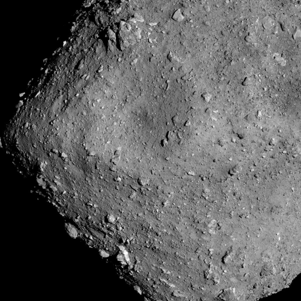
Hayabusa2 status(the week of 2018.7.23)
This week, we returned from the 6km altitude BOX-C to BOX-A, staying at an altitude of 20km±1km while images taken at BOX-C were downloaded. The images released on July 25 showed a detailed view of the unevenness of Ryugus surface. Meanwhile, we conducted a test on the laser distance measurer, LIDAR, in preparation for the Middle Altitude Observation Operation, in which the spacecraft will descend to hover at a 5km altitude and then perform the Gravity Measurement Descent Operation which decreases the altitude to just 1km. We are ready!
This week, we returned from the 6km altitude BOX-C to BOX-A, staying at an altitude of 20km±1km while images taken at BOX-C were downloaded. The images released on July 25 showed a detailed view of the unevenness of Ryugus surface. Meanwhile, we conducted a test on the laser distance measurer, LIDAR, in preparation for the Middle Altitude Observation Operation, in which the spacecraft will descend to hover at a 5km altitude and then perform the Gravity Measurement Descent Operation which decreases the altitude to just 1km. We are ready!
Next press conference is scheduled for Aug/2nd.
A new look / design of the mission web page http://www.hayabusa2.jaxa.jp/en/
This is a "lo-fi" version of our main content. To view the full version with more information, formatting and images, please click here.