Looks like the Sol 12 images are coming down
http://phoenix.lpl.arizona.edu/images.php?...3286&cID=50
Motion in the scoop for sure, so hopefully a full delivery will be imaged...in full.
Full Version: Sol 12 on onward general imaging
Hmm, it's a problem that the door not fully opened. Looks like they need first some cleaning movements with the scoop to be able to open the adjacent door then (if it's feasible at all).
The partially open door hasn't been a problem at all - there's load of material in and around the mesh, which means the oven will have got a sample. The opening of the next door will almost certainly flick the soil out of the way for the next sample.
Using the arm to clear soil from around the TEGA inlets is a bit like clearing dust from the MER solar arrays with the RAT. Wrong tool to do a bad job.
Doug
Using the arm to clear soil from around the TEGA inlets is a bit like clearing dust from the MER solar arrays with the RAT. Wrong tool to do a bad job.
Doug
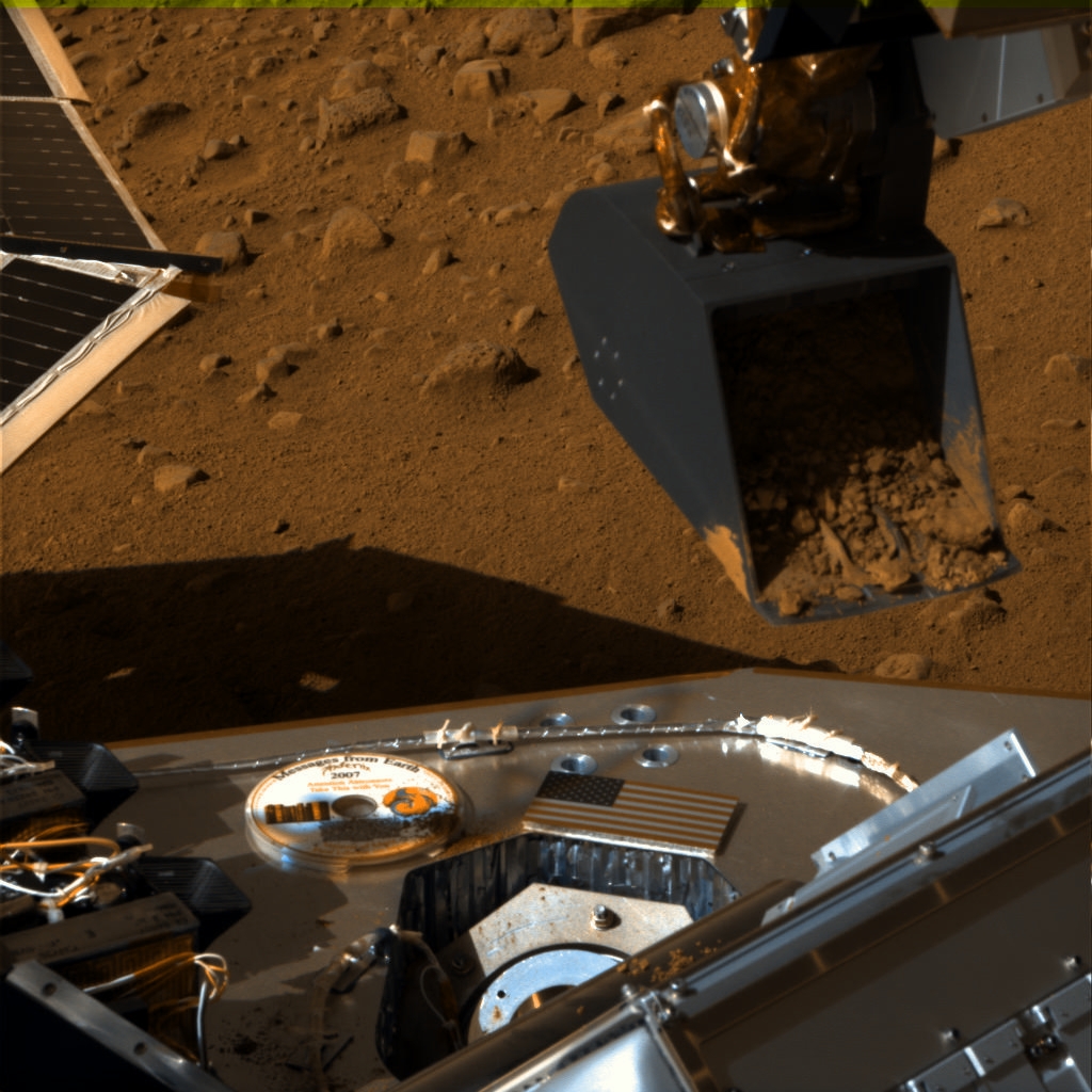
Sol 12 images of the digging area:


So the scoop that got dumped came from the dig to the right of the original dig?
That's quite a mess on the ovens, I hope the doors on the adjacent oven can clear it without contamination of the later samples by soil falling back in, I'm sure they've thought of these things. I didn't realize they'd be dumping that much on the oven!
Kung
That's quite a mess on the ovens, I hope the doors on the adjacent oven can clear it without contamination of the later samples by soil falling back in, I'm sure they've thought of these things. I didn't realize they'd be dumping that much on the oven!
Kung
Seems to me they needed a narrower scoop.
The partially opened door has clearly resulted in a less than ideal post-dump situation. I guess we will have to wait for the next press conference to see whether that much spillage will be considered a problem for either getting the doors fully open (the left one shouldn't be a problem) or for dirt from the first sample falling into the hopper and messing up the results. Perhaps they will decide to skip that chamber and only use it as a last resort if they require that many samples.
Brian
Brian
Animated GIF (1.3 MB) showing the deck before (11:30 AM) and after the dump (about 14:00):

EDIT: Updated with full resolution version.

EDIT: Updated with full resolution version.
QUOTE (elakdawalla @ Jun 7 2008, 11:07 AM) 
Emily,
I love the use of the color labels!
QUOTE (MahFL @ Jun 7 2008, 10:37 AM)
Seems to me they needed a narrower scoop.
The scoop does have a "funnel" mechanism built in but too much soil will overwhelm it.
Airbag
QUOTE (MahFL @ Jun 7 2008, 04:37 PM)
Seems to me they needed a narrower scoop.
But then it would take 12 months to dig a good trench

Doug
I suspect the soil does not flow into the funnel at all, and the soil all sticks together and slides out in one lump.
QUOTE (djellison @ Jun 7 2008, 05:17 PM)
But then it would take 12 months to dig a good trench
Doug
Doug
The trench will only be as deep as the topsoil, and that seems about 5 cm. A narrow tench is also a good trench. Seems to me the scoop is four times as wide as the oven doors which makes no sense to me. Surly the accuracy of the RA can deliver soil to any 1 cm spot it can reach ?
QUOTE (MahFL @ Jun 7 2008, 12:33 PM)
The trench will only be as deep as the topsoil, and that seems about 5 cm. A narrow tench is also a good trench. Seems to me the scoop is four times as wide as the oven doors which makes no sense to me. Surly the accuracy of the RA can deliver soil to any 1 cm spot it can reach ?
You might consider the fact that the programs to run the robotic arm were developed in Earth Gravity, with an attempt to lower it's gravity to Mars. Still, it's quite difficult to do so, and I'm sure it wasn't perfect... 1 cm is alot to ask of it all things considered. I think they'll manage to improve it over time, but still, we can only expect so much.
I'm certain this isn't somethng they haven't seen in the testing phase and have contingencies planned. They will look at this in their usual, methodical way and fix it.
Sol 13 images have arrived on the UA site.
Looks to me that the "white layer" has changed its appearance from earlier sols:
http://phoenix.lpl.arizona.edu/images.php?...3455&cID=51
Looks to me that the "white layer" has changed its appearance from earlier sols:
http://phoenix.lpl.arizona.edu/images.php?...3455&cID=51
Looks about the same to me, you may well be comparing unlike filters.
Doug
Doug
These two are from the same filter (RC, right blue) from sols 9 and 13:
http://phoenix.lpl.arizona.edu/images/gallery/lg_2984.jpg
http://phoenix.lpl.arizona.edu/images/gallery/lg_3455.jpg
The local solar time is about 1.5h later in the sol 9 image.
Exposure settings could explain the difference too.
http://phoenix.lpl.arizona.edu/images/gallery/lg_2984.jpg
http://phoenix.lpl.arizona.edu/images/gallery/lg_3455.jpg
The local solar time is about 1.5h later in the sol 9 image.
Exposure settings could explain the difference too.
I don't see any difference that isn't explained by phase angle effects. Here's a flicker gif between sol 12 (lower sun elevation) and sol 13 (more overhead). The regolith is strongly backscattering, while the mystery stuff is less phase angle dependant, suggesting non-powdery (crystalline?) makeup.

I think you got the left-right wrong in the second anaglyph, Stu. The terrain in the first anaglyph is by my calculations about 6.7 meters from the lander, almost exactly due east. HiRISE images of the lander show nothing exceptionally rough in that direction, in fact, it looks even less rugged than in other directions.
Thanks, I'll check on that second one when I have time. As for the first one, I think that's a very small area we're looking at, not a wide swathe of the landscape. More like a "crossover" area between polygons, perhaps..?
Edit: I've found where that first 3D view is centred on... 85-90deg azimuth...
Click to view attachment
Edit: I've found where that first 3D view is centred on... 85-90deg azimuth...
Click to view attachment
QUOTE (Stu @ Jun 8 2008, 03:39 PM)
I've found where that first 3D view is centred on... 85-90deg azimuth...
Wow, that's a great anaglyph of impressive-looking relief; at a guess, 30cm vertical relief with a slope of 30-40 degrees. Not a comfortable place to land I guess... imagine if the robot arm was left flailing in the air unable to contact the ground....

Just re-done that second anaglyph and I'm pretty sure the L/R are the right way round.
Remember that the separation of the SSI cameras is more than double your eye's separation, which should exagerate the 3D effect. (Of course the size/distance of the image on your display matters too, as we've discussed here before.) Incidentally that camera separation is still only about half of that on the rover pancams.
Still, I was surprized too by the relief in that first anaglyph, Stu!
Still, I was surprized too by the relief in that first anaglyph, Stu!
Thanks for the feedback on the 3Ds Fred, much appreciated. I had, to be perfectly honest, forgotten about the separation issue, so I guess that does make things look a bit more dramatic than they really are, but still, it shows there is some relief in the landscape.. can't wait to see the proper hi-resolution versions of these...
Click to view attachment
Click to view attachment
Click to view attachment
Click to view attachment
QUOTE (ugordan @ Jun 8 2008, 01:23 PM)
I don't see any difference that isn't explained by phase angle effects. The regolith is strongly backscattering, while the mystery stuff is less phase angle dependant, suggesting non-powdery (crystalline?) makeup.
Indeed, there's no evidence for a temporal change in the white material (sublimation or whatever), but those phase effects are certainly interesting! I don't think we saw this kind of behaviour for any white material dug up by Spirit! Thanks for this image, Gordan.
QUOTE
. Here's a flicker gif between sol 12 (lower sun elevation) and sol 13 (more overhead). The regolith is strongly backscattering, while the mystery stuff is less phase angle dependant, suggesting non-powdery (crystalline?) makeup.
That makes sense. The regolith is very fine and cohesive, which gives the visual texture of a granular material. I'd suspect that the particle size distribution peaks at the fine end with aeolian "clay-sized" particles and at th ecoarse end with sand to cobble-sized particles derived from ejecta, consolidated sediments/volcanics/etc and the weathering products thereof. The properties of the fines remind me a lot of "fly ash" from a coal-fired steam plant.I'm not going to stick my neck out too far, but the white material in the bottom of trhe trench initially impressed me as translucent in appearance, and still does at second look.

--Bill
Suggestive "staining" in the scoop;

It can't be what it looks like, so what is it? (blue filter) Interesting distribution in the bottom of the "funnel", and on the downslope sides of the edge of the bevel at the front of the shovel, and of the sides of the "funnel" in the floor of the scoop. What's different at those locations? I don't think it can be where the metal's been scraped clean of dust by the motion of the sample sliding onto TEGA, because it's a different colour than the pristine upper portions of the scoop.
It can't be what it looks like, so what is it? (blue filter) Interesting distribution in the bottom of the "funnel", and on the downslope sides of the edge of the bevel at the front of the shovel, and of the sides of the "funnel" in the floor of the scoop. What's different at those locations? I don't think it can be where the metal's been scraped clean of dust by the motion of the sample sliding onto TEGA, because it's a different colour than the pristine upper portions of the scoop.
Not a blue filter - blue LED's turned on. All I'm seeing is places where the scoop is clean, and places where it is not.
Doug
Doug
Yeah, I agree.
This may also partially obviate the cross-sample contamination problem from the spillage. Clearly the scoop's not gonna be perfectly clean each time, so any fall-ins are just a bit more in the load; unavoidable.
What interests me is just why the soil is both cohesive and "sticky". Gotta be pure electrostatics from the dry, dry environment combined with the extremely fine nature of the material. I wonder how many DC volts you might measure between two copper posts about 100m apart. (Probably not much due to the random distribution of charges in the soil, but more then you'd see even in Death Valley on Earth, I bet.)
I'm not seeing much discussion of the possibility that the failure is in the sensor that's supposed to detect that material is in the oven. Not sure why that should fail, but it's worth mentioning.
--Greg
--Greg
Indeed. That possibility cannot be ignored.
I apologize if this concept has already been suggested. I am on the road and finding it difficult to keep up with all messages in these threads. Is it possible that the apparent particle-clumping is caused by hygroscopic salts depressing the freezing point of water in this environment? Is that even possible at these temperatures and pressures?
I apologize if this concept has already been suggested. I am on the road and finding it difficult to keep up with all messages in these threads. Is it possible that the apparent particle-clumping is caused by hygroscopic salts depressing the freezing point of water in this environment? Is that even possible at these temperatures and pressures?
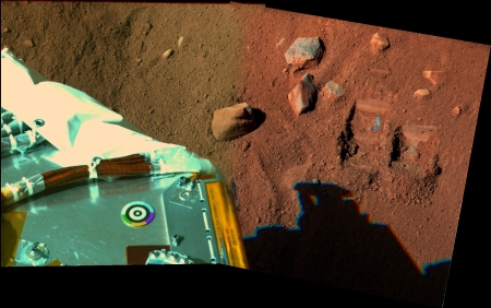
Sol 12 pictures colored by myself
The robotic arm :

And two frames stitched together who showing the two trenches and a part of the lander deck :
The robotic arm :
And two frames stitched together who showing the two trenches and a part of the lander deck :

Couple more 3Ds for ya'll... regardless of any distortion due to the separation of the cameras, etc, I still think these show the landing site is pretty cool!
Click to view attachment
Click to view attachment
Click to view attachment
Click to view attachment
Keep the good work up Stu, we all appreciate it. I tried making my own but could not find the matching pairs on the UA website.
Thanks Stu, looking forward to at 360° 3D pano
I feel we are lucky Phoenix landed leveled
I feel we are lucky Phoenix landed leveled
Level ? It's off by 1/3 of a degree, they should have included screw adjustments on the legs........ 
There's an intriguing bright (specular?) spot unearthed after the latest dig in the Dodo trench (the false color image on the right is overexposed in the green and blue channels):
Click to view attachment
It's so bright that in certain filters (notably green and blue, but also in red) it saturates the CCD causing "bleed". The exposures do seem a bit on the high side in this sequence, but this speck is obviously bright. A big salt crystal?
Click to view attachment
It's so bright that in certain filters (notably green and blue, but also in red) it saturates the CCD causing "bleed". The exposures do seem a bit on the high side in this sequence, but this speck is obviously bright. A big salt crystal?
... on the subject of "bright", there's an interesting looking bright patch over there...
Click to view attachment
... which looks like this when anaglyphalised (made up word, I know)
Click to view attachment
Click to view attachment
... which looks like this when anaglyphalised (made up word, I know)
Click to view attachment
Sorry if this has been covered before, I've been trying to catch up and I've read this and the previous imaging thread. However, I can't find the answer to this:
Why is the "bright patch" inside the first scoop trench not so bright in the latest images? Is it because the images have been taken through different filters than before, and now the spectrum is much more closer to 'natural' color? Or has it somehow changed over time? I read something about phase changes in the patch, but I assume those are caused by the different light exposure rather than by changes in the material itself?
And if it turns out this material has changed, what are the hypothesis about its nature?
QUOTE (Stu @ Jun 9 2008, 04:38 PM)
... which looks like this when anaglyphalised (made up word, I know)
hey Stu, you've become an accomplished anaglyphographer!

Wow, I think that's the first time I've seen NASA use the term "whirligig" in an official document
They also mention that it has a "black hole." Perhaps they need to increase the Schwarzschild radius to allow particles to pass into the oven? 
This is a "lo-fi" version of our main content. To view the full version with more information, formatting and images, please click here.