Very nice animation Bjorn. It's fun to try and recognize various features as you fly over. One example is the sequence starting at 4:55 when the crater Sabur is centered in the view. Then from 5:00 to 5:12 we are flying northbound alongside Anbar Fossae. At 5:21 we're transitioning from Samarkand Sulci to Hamah Sulci (note unnamed crater at that time), then about 5:30 when flying from Hamah Sulci down to Ebony Dorsum.
Earlier at 2:23 we come upon a double crater, the one on the right side being Al-Mustazi. We approach the northern part of Bishangarh Fossae at 2:26. Then we catch the western part of Al-Yaman Sulci (oriented from left to right) around 2:33. By 2:43 we swing to look at the southern end of Harran Sulci (towards the west). At 2:49, we are looking westward at the northern end of Khorasan Fossa. At 3:00 we spot the intersection of Harran Sulci and Kaukaban Fossae near the limb. Then by 3:07 the crater Harun is located above the center. The southbound canyon fly through at 3:30 looks like we're going back through the southern end of Harran Sulci.
Perhaps the makings of a narrated sound track?
Things like the serrated limb help to make this look very realistic. Might be interesting to consider texture and even some slight color at some point?
Steve
Full Version: Enceladus PDS image products
QUOTE (scalbers @ Mar 4 2012, 09:38 PM) 
Might be interesting to consider texture and even some slight color at some point?
On the contrary, I think Bjorn nailed the color here.

Interesting to watch the phase angle effects as well, it's clear right from the initial frame that the photometric modelling of the disc is more realisic than what one would expect from just illuminating a ball in a commercial 3D renderer. About the only thing that gives away the fact this is a rendering is the lack of secondary illumination of shadowed slopes near the terminator by the opposing sunlit slopes. Other than that, add some point spread function and this could pass under an actual Cassini image.
It looks fantastic Bjorn!
Can you make some anaglyph versions?
Can you make some anaglyph versions?
QUOTE (scalbers @ Mar 4 2012, 08:38 PM)
Very nice animation Bjorn. It's fun to try and recognize various features as you fly over. One example is the sequence starting at 4:55 when the crater Sabur is centered in the view. Then from 5:00 to 5:12 we are flying northbound alongside Anbar Fossae. At 5:21 we're transitioning from Samarkand Sulci to Hamah Sulci (note unnamed crater at that time), then about 5:30 when flying from Hamah Sulci down to Ebony Dorsum.
[snip]
Perhaps the makings of a narrated sound track?
Things like the serrated limb help to make this look very realistic. Might be interesting to consider texture and even some slight color at some point?
Steve
[snip]
Perhaps the makings of a narrated sound track?
Things like the serrated limb help to make this look very realistic. Might be interesting to consider texture and even some slight color at some point?
Steve
A narrated sound track - that's an interesting idea. And it's nice to see there are lots of recognizable features there ;-). Regarding texture, it wouldn't add any details since compared to the original images, loss of resolution is negligible in the DEM.
QUOTE (ugordan @ Mar 4 2012, 08:47 PM)
Interesting to watch the phase angle effects as well, it's clear right from the initial frame that the photometric modelling of the disc is more realisic than what one would expect from just illuminating a ball in a commercial 3D renderer. About the only thing that gives away the fact this is a rendering is the lack of secondary illumination of shadowed slopes near the terminator by the opposing sunlit slopes. Other than that, add some point spread function and this could pass under an actual Cassini image.
I'm using a slightly modified version of the earliest Hapke function - it's modified to avoid unrealistic effects when the emission angle approaches 90 degrees. The phase effects are interesting and very strong. I even had to reduce the opposition effect a bit to avoid problems with dynamic range.
The lack of completely black shadows (no secondary illumination) is a problem and makes terminator closeups less realistic. The only reason I avoided them was to speed up the rendering time. Adding a point spread function is a nice idea but some of my test renders look realistic to me anyway. A year or two ago I somehow managed to confuse an Enceladus test render with a Cassini image for a few seconds. Needless to say I was happy when I realized what had happened.
QUOTE (machi @ Mar 5 2012, 10:21 AM)
It looks fantastic Bjorn!
Can you make some anaglyph versions?
Can you make some anaglyph versions?
That's probably a bit complicated due to the complicated flight path. A bigger problem is rendering time even though my renderer is at least two times faster now than it was two months ago. But this might be an interesting future project.
nice
It might be my imagination but
did you use ISIS to " destripe "
I have been reprocessing the venus data and have been seeing that X cross hashing every where
It might be my imagination but
did you use ISIS to " destripe "
I have been reprocessing the venus data and have been seeing that X cross hashing every where
I used ISIS' dstripe 'indirectly' - the dstripe documentation contains a fairly detailed description of the algorithm used to destripe and this enabled me to implement this capability in my own software. I've mainly been using ISIS to correct the camera angles (jigsaw, deltack etc.).
Regarding the "X cross hashing" - if this is what I think it is I've seen it too. I've found that fairly often after I destripe, new narrow and fainter stripes appear that have an orientation that differs from the orientation of the original stripes. When this happens I need to rotate the DEM (to make the new stripes horizontal), destripe again end rotate the DEM back. Sometimes I need to do this several times. Sometimes this is a prolonged trial and error process.
Regarding the "X cross hashing" - if this is what I think it is I've seen it too. I've found that fairly often after I destripe, new narrow and fainter stripes appear that have an orientation that differs from the orientation of the original stripes. When this happens I need to rotate the DEM (to make the new stripes horizontal), destripe again end rotate the DEM back. Sometimes I need to do this several times. Sometimes this is a prolonged trial and error process.
QUOTE (Bjorn Jonsson @ Mar 4 2012, 12:14 PM)
A lot of stereo coverage is available but I haven't done this yet since it takes a lot of time - I may do it later.
Do you have a list of stereo pairs that could be processed? ISS images usually process pretty quickly in ASP and would make a fun test case for me. I could then share my results back to you via this thread.
Not a list but the March and July 2005 flybys provided lots of stereo coverage since there is a lot of overlap - the March flyby was equatorial and the July flyby south of the equator with the illumination geometry almost identical.
Stereo pairs from these flybys are easy to find - one example is images N1500059045_2.IMG (July) and N1489045316_2.IMG (March).
There is also stereo coverage from later flybys but I'm not yet familiar with the details of these flybys.
Stereo pairs from these flybys are easy to find - one example is images N1500059045_2.IMG (July) and N1489045316_2.IMG (March).
There is also stereo coverage from later flybys but I'm not yet familiar with the details of these flybys.
Bjorn,
That flight was tremendous! Thanks for sharing your hard work.
You and your work are an inspiration.
~pdp8e
That flight was tremendous! Thanks for sharing your hard work.
You and your work are an inspiration.
~pdp8e
I'll second that. 
QUOTE (Bjorn Jonsson @ Mar 5 2012, 11:10 PM)
I'm using a slightly modified version of the earliest Hapke function - it's modified to avoid unrealistic effects when the emission angle approaches 90 degrees. The phase effects are interesting and very strong. I even had to reduce the opposition effect a bit to avoid problems with dynamic range.
Outstanding video Bjorn! Amazing!

I loved the phase-angle effects too. Could you elaborate on the modified version of the earliest Hapke function or point to where that function can be found? Those zero-phase glares are very prominent on the Moon/lunar surface too, but I suspect generally on any body with rough surfaces.
Thank you very much for any pointers!
Edit: Is this what you've been working with? -> http://selena.sai.msu.ru/Pug/Publications/ms42/m42_60.pdf
Rafael
The modified Hapke function I'm using can be found in my software and (probably) nowhere else ;-). What I'm doing is a crude (probably), simple and empirical modification: I'm preventing the emission angle from ever getting 'too close' to 90 degrees by multiplying it with a number that is a slightly lower than 1 once the emission angle exceeds ~80 degrees. This number is actually a function of the emission angle and gets a bit lower as the emission angle approaches 90 degrees. This may seem strange but since the patch of surface within a pixel really is never perfectly smooth the average emission angle of the visible 'facets' within the pixel should never get extremely close to 90 degrees. This is simpler (but also less accurate) than the more complicated forms of the Hapke functions and eliminates unrealistic bright 'rims' around some terrain edges or planetary discs.
Thank you very much Bjorn for the insight!
On November 27, 2016 Cassini at last obtained really good images of Enceladus' north pole during a nontargeted flyby. This is a mosaic of two IR3-GRN-UV3 color composites processed to show Enceladus in approximately natural color and in greatly exaggerated color which reveals compositional variations. A version with a latitude/longitude grid is also included.
Click to view attachmentClick to view attachmentClick to view attachment
The images comprising the mosaic were obtained at a range of 62,000 to 72,000 km. ISIS3 (qnet/jigsaw) was used to correct the camera pointing. I then reprojected everything to simple cylindrical projection and rendered the images using software I wrote. The final step was to use Photoshop to process the color.
The highest resolution view of the north pole obtained during this flyby is a clear filter image at a range of 32,000 km. The resolution is 190 m/pixel:
Click to view attachmentClick to view attachment
Monochrome image mosaic of Enceladus taken during the targeted E10 flyby, at a distance of 40,000 km
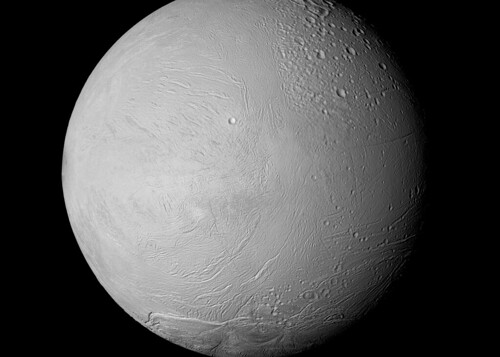 Enceladus - Rev 131 Flyby - 2010-05-18
IR3, GRN, UV3 extended color mosaic taken a little closer, from a distance of ~20,000 km.
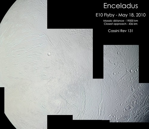 Cassini - Enceladus E10 Mosaic - Rev 131 - 05-18-2010
Both mosaics primarily target the equatorial regions of the leading hemisphere between about 200E and 0E.
Enceladus - Rev 131 Flyby - 2010-05-18IR3, GRN, UV3 extended color mosaic taken a little closer, from a distance of ~20,000 km.
Cassini - Enceladus E10 Mosaic - Rev 131 - 05-18-2010Both mosaics primarily target the equatorial regions of the leading hemisphere between about 200E and 0E.
This is a "lo-fi" version of our main content. To view the full version with more information, formatting and images, please click here.