Viking '75 Mars Lander Construction, Looking for Viking lander design/construction information |

  |
Viking '75 Mars Lander Construction, Looking for Viking lander design/construction information |
 Jun 7 2023, 02:43 PM Jun 7 2023, 02:43 PM
Post
#76
|
|
|
Member  Group: Members Posts: 939 Joined: 4-September 06 From: Boston Member No.: 1102 |
Thank you Tom. The models and writeup are outstanding. It is fascinating to see and read about all that went into making the RTG as reliable and safe (to accident) as possible.
-------------------- |
 |
 
|
|
Jun 7 2023, 03:37 PM
Post
#77
|
|
|
Senior Member Group: Members Posts: 2546 Joined: 13-September 05 Member No.: 497 |
Great post on the RTGs, Tom! Looking forward to seeing them integrated into the overall model. I've never been sure of exactly where they were, as they are underneath a cover and not shown well in most extent drawings and photos.
It's a little surprising to me that having the RTGs "inside" was the configuration they chose (with a "thermal switch"* to control the conduction between the RTG and the equipment plate). MSL and M2020, of course, have their RTGs outside with a fluid loop to bring in the heat. Seems like it would get pretty hot under the RTG cover. * https://ntrs.nasa.gov/api/citations/1981000...19810001592.pdf page 34. -------------------- Disclaimer: This post is based on public information only. Any opinions are my own.
|
|
|
|
|
Jun 7 2023, 11:08 PM
Post
#78
|
|||
 Member Group: Members Posts: 101 Joined: 3-May 12 From: Massachusetts, USA Member No.: 6392 |
Indeed it surely was pretty hot within the lander's wind covers, given that the RTG exterior housings were over 300F continuously. Even so, the conduction and radiation of heat into the lander was not sufficient during cold winter nights, thus the need for thermal switches used to occasionally provide a higher-efficiency conduction path under each RTG's front edge. (An earlier reply above has details of those thermal switches.) I think the rationale for enclosing the Viking lander's RTGs was due to lack of knowledge of Martian surface winds, and to some extent of surface pressure and gas composition. The covers were a strategy to avoid loosing too much heat to worst-case estimated winds; the risk of over-heating was apparently deemed minimal.
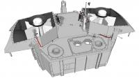
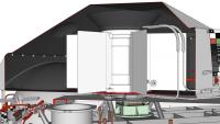
Regarding the installation of the RTGs, I have almost completed modeling the associated wind covers and their internal framework and fasteners, the RTG Upper and Lower End Cap Coolers and their plumbing, etc. Here is a sneak peak at the RTGs and wind covers on a partial lander for context:
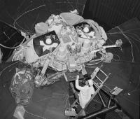
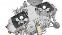
And here is a historic image from Martin Marietta showing the Proof Test Capsule lander (now in the Smithsonian National Air and Space Museum) without the wind cover tops. In this image instead of RTGs there are two ETGs installed - Electrically-heated Thermoelectric Generators: nearly identical to the RTGs but with an electric heater block instead of a Plutonium fuel capsule. The electric cable leading into the ETG reservoir dome is the indication of ETG vs. RTG.
In both my 3D model rendering and the historic photo the black conical objects on top of the RTG/ETG (and within which the reservoir dome is situated) are Upper End Cap Coolers. You can see the coolant loop tubing that enters and exits the front edge of the cooler near the top of the RTG/ETG. The Lower End Cap Coolers are not visible due to the angle I chose in the 3D rendering, but one is barely visible under the left ETG in the historic photo. It is a black flat disc with a large cutout to accommodate the giant bulge in the wind cover bottom to avoid the fuel tank. An edge of the LECC is just visible at about the 7 o'clock position between ETG radiator fins. In the historic photo the massive plastic-wrapped hoses that encircle the ETG on the right (and that snake around behind the lander) are providing the coolant to the lander's coolant loop. The internal path of the coolant loop is visible in some of my earlier 3D renderings in posts above. |
||
|
|
|
||
|
Jul 15 2023, 06:57 PM
Post
#79
|
||||
|
Member Group: Members Posts: 101 Joined: 3-May 12 From: Massachusetts, USA Member No.: 6392 |
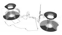
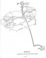
I have completed integrating the SNAP-19 Viking RTGs into my work-in-progress Viking '75 Mars lander 3D model. Here are renderings of the coolant loop, from above and below, that was used prior to launch to remove excess heat from the RTGs and lander interior. The RTGs directly generated electricity from the copious amount of heat produced by radioactive decay of plutonium 235 fuel within each RTG. The RTGs and associated integration mechanisms were designed for the Mars surface environment, which is very low pressure and quite cold. Earth's warm higher-pressure atmosphere caused excessive heating of the lander after the RTGs were installed during the final few months prior to launch. Sterilized chilled water was circulated through the loop almost without interruption (even during the lift of the shrouded orbiter and lander capsule onto the Titan launch vehicle) until shortly before launch. At that point, the coolant was purged with hot dry sterile nitrogen gas, and then a pyrotechnic cutter severed the lines within the Base Cover (top half of the inner layer of the lander capsule). This elaborate procedure was used to avoid unsealing the bioshield (outer layer of the capsule within which the sterilized lander was enclosed) and contaminating the lander with Earthly spores and microbes.
The large black objects affixed to the top and bottom of the RTGs (seen in transparent form to better reveal coolant loop components) are passive End Cap Coolers (ECCs). The coolant circulated through tubing embedded within the ECCs to carry away some RTG heat, and the large surface area of the conical upper ECC and the flat disk lower ECC radiated additional heat. The loop was also used during the two-day complete-capsule sterilization procedure, temporarily replacing the chilled water with hot water to speed up heating the lander interior (otherwise the lander body's insulation would require a much longer heat soak period).
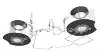
Here is an historic diagram of the coolant loop and N2 purge line (a simplified form of which is included in the model, see subsequent replies, but not shown above).
|
|||
|
|
|
|||
|
Jul 15 2023, 07:48 PM
Post
#80
|
|||||
|
Member Group: Members Posts: 101 Joined: 3-May 12 From: Massachusetts, USA Member No.: 6392 |
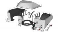
Here are exploded views of the wind cover for RTG #2. The two wind covers are nearly-identical mirror images of each other. They differ primarily in small items attached to the front face of the wind cover, and that the top of wind cover #2 has an indentation for clearance of the Low Gain Antenna which is located very close to the wind cover. As can be seen, the wind covers are more complicated than they perhaps appear. Each wind cover has internal stiffening ribs along the side and an internal panel near front-center. Each wind cover has a large circular vent on its bottom face near a front corner (visible left of center in the second exploded view below). The vent allows equalization of pressure during launch from Earth and landing on Mars, and is covered with fine mesh to filter out most Martian atmospheric dust. Each wind cover has a camera Reference Test Chart (RTC) attached to its front face. The RTC itself is exploded in these views. A small skirt surrounds the sides and front of the wind cover bottom edge, to minimize build-up of Mars dust under the wind cover during the mission.
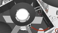
Here are close-up views of RTG 2 within its wind cover, starting with a top view. The large conical Upper End Cap Cooler (ECC) is prominent surrounding the reservoir dome atop the RTG housing. The rear rim of the ECC is clipped for clearance within the sloping top of the wind cover. The curving coolant loop inlet and outlet lines are prominent in the upper right of the image. The flat disc radiator fin of the lower ECC blends into the black interior of the wind cover bottom, but it is quite large and obvious when you know what to look for. The rear edge of the radiator fin is also clipped to clear the wind cover's large spherical inward-bulging rear which in turn provides clearance for the lander's nearby propellant tank. The large red cable in the lower right carries the 4.4 volt DC electric output of the RTG, along with six instrumentation signal lines (two each for an internal pressure transducer, a fin root thermistor which measured the temperature of the interior surface of the RTG housing, and a Resistive Temperature Detector (RTD) which measured the temperature of one of the thermocouple pairs surrounding the RTG's internal heat source). The small cream-colored cable passing through an electrical connector near bottom-center delivers the signal from a hazard monitor thermistor which measured the exterior temperature of the RTG housing.
Here is a side view of RTG and wind cover 2 that is cut away to reveal RTG mounting details. The lower ECC has a flattish gray (I believe cast aluminum) body with a somewhat irregular shape. The coolant loop lines enter and exit from the right portion of the ECC body. Four stout tabs (only one of which is easily visible here below-center of the image) mount the ECC, and thus the RTG and wind cover, to the lander structure. The ECC's two inboard tabs are supported on titanium (for low thermal conductance) U-channel tripods and bipods (with lightening holes) that are in turn mounted to the Equipment Plate within the upper interior of the lander. The green-tinted object between the tripod and bipod and below the RTG front edge is a Thermal Switch for transferring variable amounts of RTG heat into the lander. The ECC's two outboard tabs bolt to small extensions of the lander body side beam structure. The lower ECC's flat disc radiator fin is cut away to better reveal the ECC body below the fin. The disc fin is thin on its outer perimeter, thickening toward its slightly depressed center. The dark conical upper ECC is easily visible atop the RTG housing, and the coolant loop inlet and outlet lines can be seen passing into the upper ECC base. The larger-diameter striped segments of the coolant loop represent braided flexible hoses used in that area. The remainder of the coolant loop is rigid 0.25 inch tubing.
|
||||
|
|
|
||||
|
Jul 15 2023, 07:51 PM
Post
#81
|
|||
|
Member Group: Members Posts: 101 Joined: 3-May 12 From: Massachusetts, USA Member No.: 6392 |
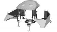
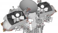
Here are renderings of the entire RTG installation of the work-in-progress lander model, without the RTG wind cover tops to reveal the RTGs and details within. Compare these to a historic photo posted a few replies back.
|
||
|
|
|
||
|
Jul 15 2023, 07:56 PM
Post
#82
|
||
|
Member Group: Members Posts: 101 Joined: 3-May 12 From: Massachusetts, USA Member No.: 6392 |
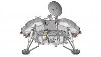
Lastly (for now!) here is an overall view of the work-in-progress lander. Various exterior components remain to be modeled, which will keep me occupied for a few more years (literally). I began the creating model in December 2013, so I'm coming up on the tenth anniversary of the project. The model is freely available as a SketchUp SKP file hosted on DropBox (note: it is nearly 400MB).
|
|
|
|
|
|
|
Jul 22 2023, 01:02 AM
Post
#83
|
|
 Member Group: Members Posts: 613 Joined: 23-February 07 From: Occasionally in Columbia, MD Member No.: 1764 |
QUOTE (Tom Dahl @ Jun 7 2023, 06:08 PM)  ... And here is a historic image from Martin Marietta showing the Proof Test Capsule lander (now in the Smithsonian National Air and Space Museum) without the wind cover tops. Amazing work, Tom. I'd never seen the RTG accommodation without the wind shields. Lots of other nice detail visible in your 3D model, like the little 'bone' energy absorbers attaching the leg bipod struts to the lander body.... Ralph |
|
|
|
|
Dec 27 2023, 11:35 PM
Post
#84
|
|
|
Member Group: Members Posts: 101 Joined: 3-May 12 From: Massachusetts, USA Member No.: 6392 |
I just completed a 21-minute video describing the Viking '75 Mars lander's two SNAP-19 Viking Radioisotope Thermoelectric Generators (RTGs) in detail. The video illustrates the RTGs using a high-fidelity 3D digital model that is a work-in-progress hobby effort of mine (for the past ten years, as of this month), see earlier replies in this topic. The WIP digital model is freely available in SketchUp format via DropBox as a 386MB SKP format file.
QUOTE (rlorenz @ Jul 21 2023, 08:02 PM) ...the little 'bone' energy absorbers attaching the leg bipod struts to the lander body.... I forgot to mention back in July that a few years ago I created a short video about the lander's legs, which mention those so-called load limiters. |
|
|
|
|
Dec 28 2023, 12:58 PM
Post
#85
|
|
 Senior Member Group: Members Posts: 1089 Joined: 19-February 05 From: Close to Meudon Observatory in France Member No.: 172 |
QUOTE (Tom Dahl @ Dec 28 2023, 12:35 AM) I just completed a 21-minute video describing the Viking '75 Mars lander's two SNAP-19 Viking Radioisotope Thermoelectric Generators (RTGs) in detail. The video illustrates the RTGs using a high-fidelity 3D digital model that is a work-in-progress hobby effort of mine (for the past ten years, as of this month), see earlier replies in this topic. The WIP digital model is freely available in SketchUp format via DropBox as a 386MB SKP format file. I forgot to mention back in July that a few years ago I created a short video about the lander's legs, which mention those so-called load limiters. Dear Tom. What an amazing work!  Congratulations: thanks to you, I'm travelling back in time. With best regards, Olivier |
|
|
|
|
Dec 28 2023, 03:12 PM
Post
#86
|
|
 Member Group: Members Posts: 716 Joined: 3-December 04 From: Boulder, Colorado, USA Member No.: 117 |
Second that- wonderful and amazing stuff, and I learned a lot about how RTGs work.
John |
|
|
|
|
Dec 30 2023, 05:28 PM
Post
#87
|
|
 Member Group: Members Posts: 132 Joined: 19-November 14 From: Québec Member No.: 7339 |
QUOTE (Tom Dahl @ Dec 27 2023, 06:35 PM) I just completed a 21-minute video describing the Viking '75 Mars lander's two SNAP-19 Viking Radioisotope Thermoelectric Generators (RTGs) in detail. The video illustrates the RTGs using a high-fidelity 3D digital model that is a work-in-progress hobby effort of mine (for the past ten years, as of this month), see earlier replies in this topic. The WIP digital model is freely available in SketchUp format via DropBox as a 386MB SKP format file. Waw ! Very good job Tom Dahl. It truly is a technological marvel! -------------------- |
|
|
|
|

|
Lo-Fi Version | Time is now: 18th October 2024 - 05:21 AM |
|
RULES AND GUIDELINES Please read the Forum Rules and Guidelines before posting. IMAGE COPYRIGHT |
OPINIONS AND MODERATION Opinions expressed on UnmannedSpaceflight.com are those of the individual posters and do not necessarily reflect the opinions of UnmannedSpaceflight.com or The Planetary Society. The all-volunteer UnmannedSpaceflight.com moderation team is wholly independent of The Planetary Society. The Planetary Society has no influence over decisions made by the UnmannedSpaceflight.com moderators. |
SUPPORT THE FORUM Unmannedspaceflight.com is funded by the Planetary Society. Please consider supporting our work and many other projects by donating to the Society or becoming a member. |
|